
Relay & Timer Modules
Timing, Modbus I/O, signal isolation and compact programmable-control modules; compare I/O assignments and ordering options.
Select Timing, I/O or Programmable Control Before the Order Code
This directory groups ordinary automation modules, not interchangeable safety controllers. Start with the control task: timed switching, distributed I/O, protocol conversion, signal isolation or compact programmable logic. A connection to a PLC does not make a relay module a safety PLC.
Compare 23 Relay & Timer Modules Series
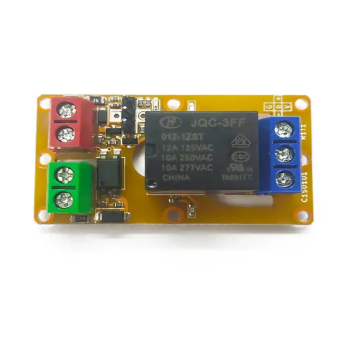
A1J0101 Economical Input Amplifier Module
Optocoupler-isolated input amplifier that turns a low-voltage signal into a 250V AC / 10A relay output.
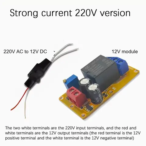
B2J0101 Economical Power-up Delay Module
Low-cost power-up delay relay module with a 2-30 second adjustable delay and no trigger input required.
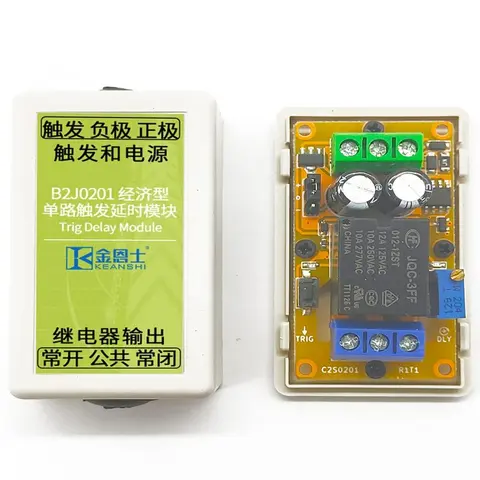
B2J0201 Economical Trigger Delay Module
Level-triggered delay relay module with jumper-selectable high/low trigger and a 2-30s adjustable delay.
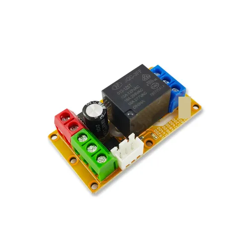
B2J0302 Enhanced Single MODBUS-485 I/O Module
Enhanced single-channel MODBUS-RTU/RS-485 I/O module: 1 digital input, 2 analog inputs, 1 relay or transistor output, AT command support and a 5V sensor supply — the successor to the discontinued B2J0301.
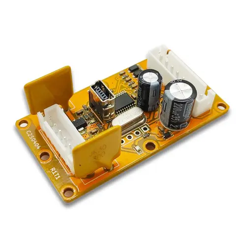
B2J0401 MODBUS Analog/Digital I/O Module
Economical MODBUS-RTU/RS-485 module: 4 analog/digital inputs plus 2 MOSFET PWM/PTO outputs.
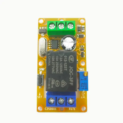
B2J0601 Economical Intelligent Trigger Delay Module
26 delay modes, seconds to hours, 30 ppm accuracy, and built-in voltage-threshold detection in one button-set module.
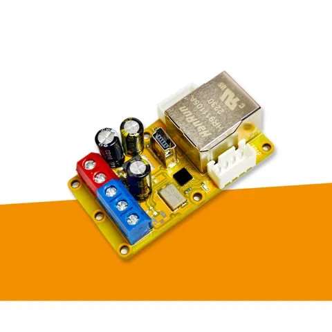
B2J0701 Ethernet to RS-485 MODBUS-TCP Gateway Module
Economical Ethernet-to-RS-485 gateway that converts MODBUS-TCP to MODBUS-RTU, offers transparent serial tunnelling, works as TCP server or cloud-connecting client, and drops a whole RS-485 field bus onto your LAN for the price of a sensor.
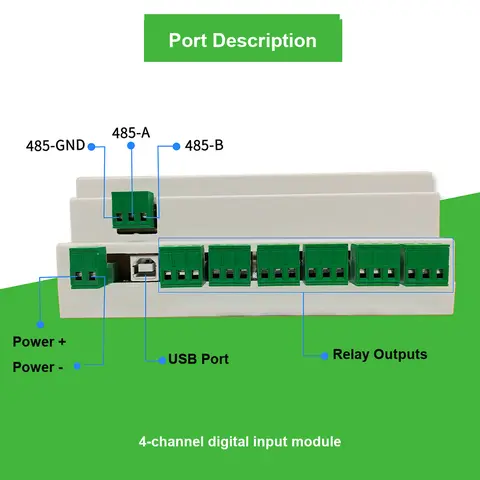
D3J0104 Modbus
A 4-channel isolated Modbus-RTU/RS-485 digital input module for distributed status monitoring.
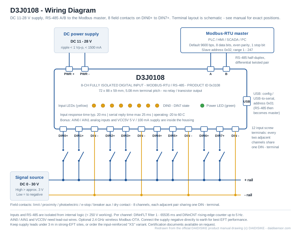
D3J0108 Modbus
8-channel fully isolated Modbus-RTU/RS-485 digital input module for machine and cabinet status monitoring.
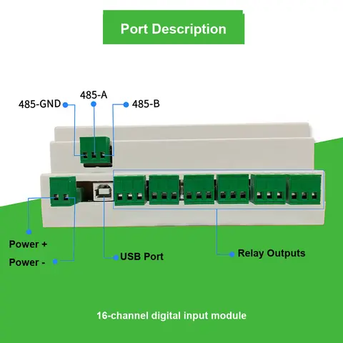
D3J0116 Modbus
16-channel fully isolated Modbus-RTU/RS-485 digital input module for centralized cabinet and line signal acquisition.
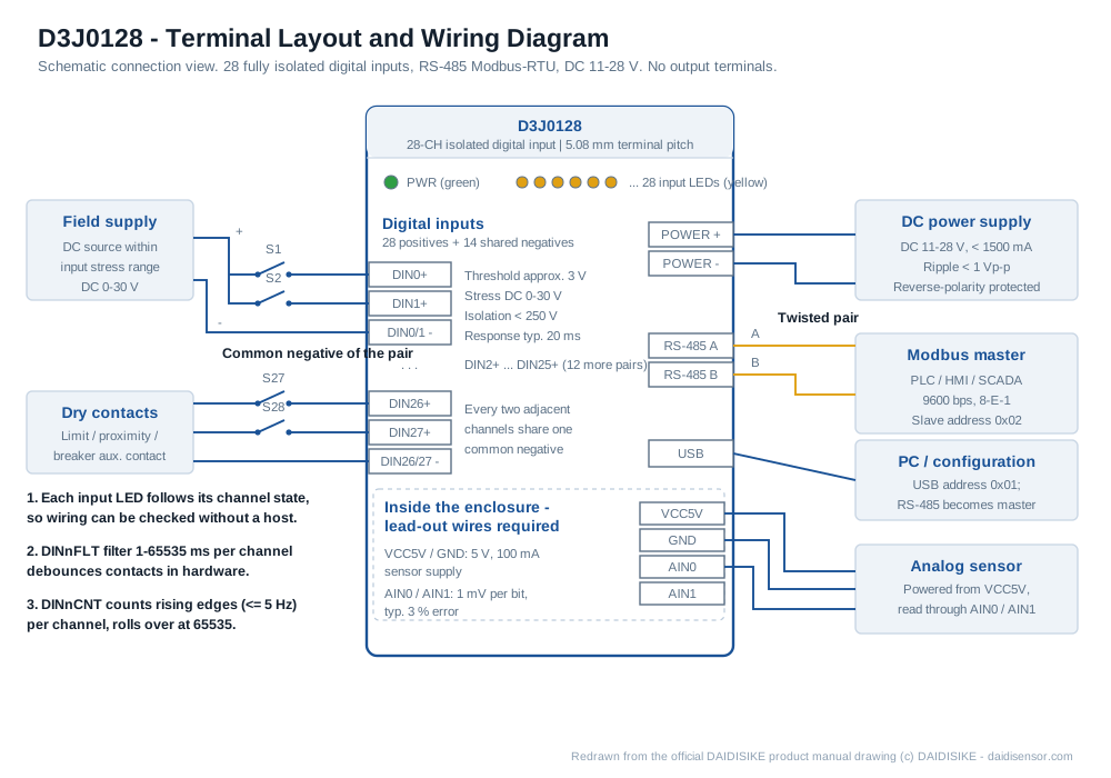
D3J0128 Modbus
28-channel fully isolated Modbus-RTU/RS-485 digital input module for high-density centralized signal acquisition.
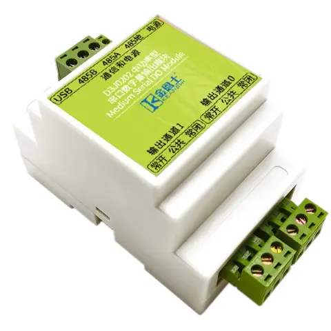
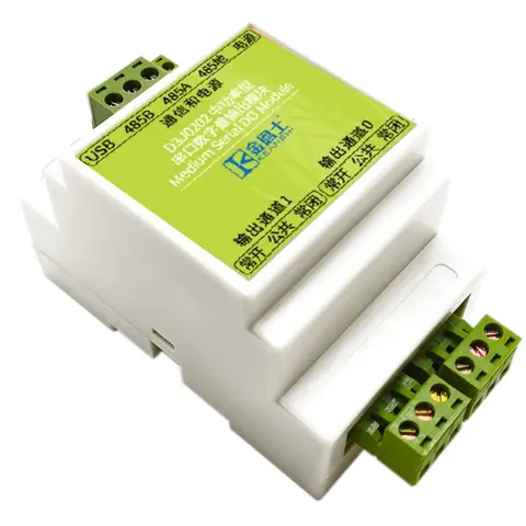
D3J0202 Modbus
2-channel Modbus-RTU/RS-485 relay/transistor output module; optional PWM/PTO uses existing DO0/DO1 channels.
D3J0204 Modbus
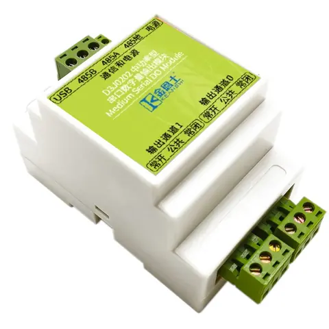
4-channel Modbus-RTU/RS-485 relay/transistor output module; optional PWM/PTO uses existing DO0/DO1 channels.
D3J0208 Modbus
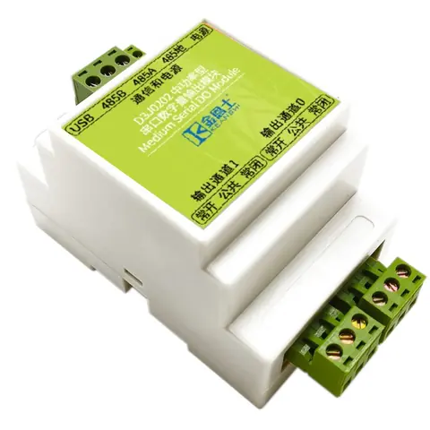
8-channel Modbus-RTU/RS-485 relay/transistor output module; optional PWM/PTO uses existing DO0/DO1 channels.
D3J0214 Modbus
14-channel Modbus-RTU/RS-485 relay/transistor output module; optional PWM/PTO uses existing DO0/DO1 channels.
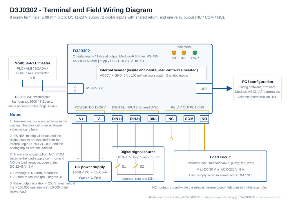
D3J0302 Modbus
2-in/1-out Modbus-RTU/RS-485 I/O module with relay/transistor output for input acquisition and local control.
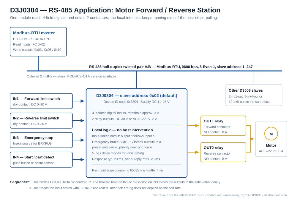
D3J0304 Modbus
A 4-in/2-out isolated Modbus-RTU/RS-485 digital I/O module that acquires and controls on one board.
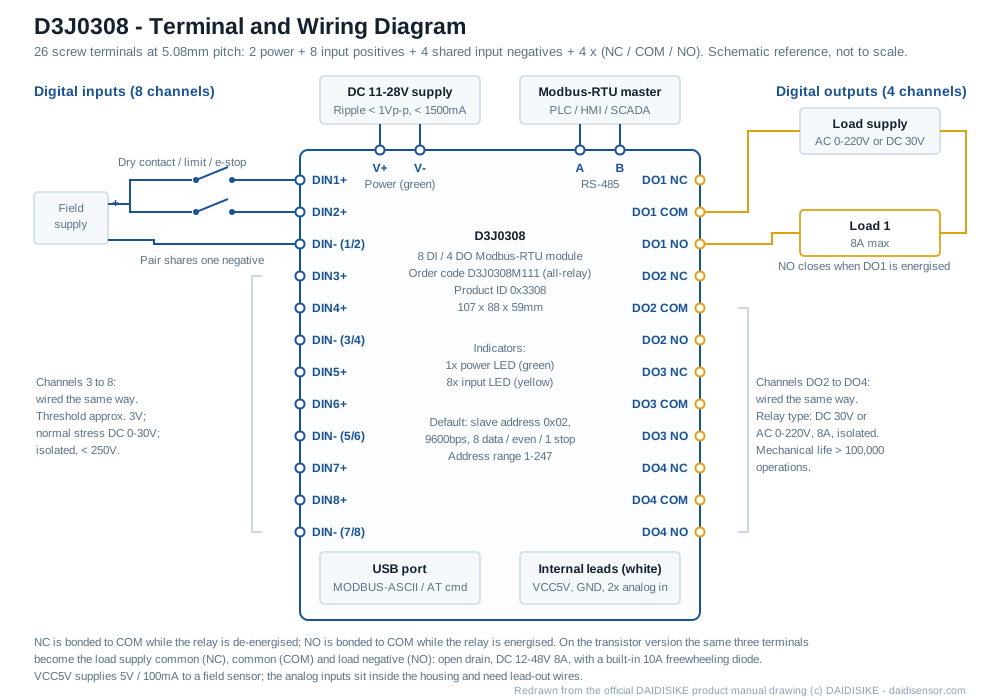
D3J0308 Modbus
8-input/4-output Modbus-RTU/RS-485 I/O module with relay or transistor outputs, local interlock and emergency braking.
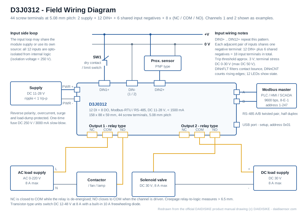
D3J0312 Modbus
12 isolated inputs + 8 relay/transistor outputs on Modbus-RTU/RS-485 - the D3J03 series' highest I/O count.
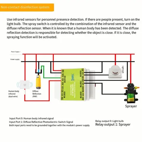
D4G0206 Relay Module
Graphical schematic-programmed micro PLC module with 6 inputs and 4 relay/transistor outputs, no ladder logic required.
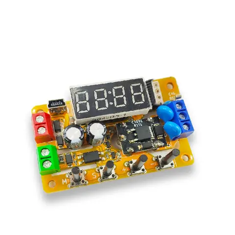
E4J0101 Easy Multifunctional Trigger Delay Module
ASIC-based delay relay with ~100 templates, ~1,000 delay modes, and optional wireless remote trigger.
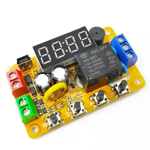
E4J0102 Easy Multifunctional Clock-Trigger Delay Module
Analog voltage-threshold triggering plus an optional real-time clock, in one multi-function delay relay module.
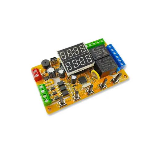
E4J0103 Easy Multifunctional Dual-Channel Trigger Delay Module
Two relay/transistor outputs, independent or linked via four modes, with 0.01% delay accuracy and ~1000 delay modes.
Compare the Configuration Paths
| Required task | Existing product page | What to confirm |
|---|---|---|
| Power-on or externally triggered timing | B2J0101 power-up timing | Compare trigger source and timing sequence with the selected B2J/E4J model. |
| Multifunction timing | E4J0101 timing configurations | Confirm the exact input, output, timing range and configuration method from its table. |
| Remote I/O configuration | B2J0401 I/O ordering options | Count digital/analog inputs and outputs separately; B2J0401 and B2J0405 are different ordering codes. |
| Ethernet to RS485 communication | B2J0701 gateway options | Confirm protocol roles, connected equipment, register access and network arrangement. |
| Compact programmable sequencing | E4J0206 programmable-control configuration | The existing page address is retained; use the confirmed E4J0206 ordering name and verify the actual I/O version. |
Specify I/O and Mechanical Options as Separate Line Items
| Purchase input | Information to provide |
|---|---|
| I/O schedule | List each input signal and each output load, including voltage, current and isolation requirements. D3J-02XX covers 2–14 outputs; select the exact channel-count model. |
| Timing or program behaviour | Provide the required sequence, trigger conditions and restart behaviour; do not assume every timer supports every cyclic mode. |
| Housing and installation | For B2J/E4J, DIN-rail mounting, bare-board supply and enclosure choices are options. State which arrangement the quotation should include. |
When the job is a protective stop, use the DA31 and DQSRN safety relay directory and verify the complete safety circuit. Ordinary programmable process modules must not replace that function.
Send the application details and required configuration through the inquiry form so that the quotation identifies the selected equipment and options.
Relay & Timer Modules in Action — 8 Demonstration Videos
Wiring, setup and live operation filmed on the actual modules. Each clip links back to the series it demonstrates, so you can go straight from footage to specification.
B2J0101 Power-On Delay Relay Module Demo — Set the Delay with One Potentiometer (5-24V)
Power the B2J0101 and the relay pulls in after the preset time — no trigger wiring at all. The clip shows the single-potentiometer adjustment and the relay switching a load across the 5–24 V supply range, the simplest way to stagger start-up of pumps, fans or control power.
B2J0201 Trigger Delay Relay Module — Signal-Triggered Timing Demo (High/Low Level Input)
A sensor pulse starts the timing cycle: the video walks through high-level and low-level trigger wiring on the B2J0201 and shows the relay following each trigger with the set delay. Watch this before wiring an NPN or PNP sensor to a delay module for the first time.
B2J0601 Intelligent Delay Relay — 12 Timing Modes, 20ppm Accuracy, One-Button Setup
One compact module covering 12 timing programs — on-delay, off-delay, cycling, one-shot and more — set from a single button and held to 20 ppm clock accuracy. The demo steps through mode selection and shows a photoelectric sensor driving the input.
Related: B2J0601 Economical Intelligent Trigger Delay Module
B2J0302 MODBUS RS-485 Relay I/O Module — Wiring & PC Control Demo (MODBUS-RTU)
RS-485 A/B wiring, slave address setup and live relay switching from a PC MODBUS-RTU master — the whole path from terminal block to register write. A practical starting point if you are putting relay outputs on a 485 bus for PLC or SCADA control.
A1J0101 Optocoupler Isolated Input Relay Module — Wiring & Trigger Demo (5-24V DC)
The A1J0101 takes a weak or noisy 5–24 V DC signal through an optocoupler-isolated input and switches a clean relay contact on the other side. The demo shows the input wiring and the isolation boundary that protects your controller from the load circuit.
E4J0101 Digital Display Delay Relay — Menu Setup & Trigger Demo (USB Configurable)
Digit-by-digit menu setup on the E4J0101 digital display delay relay, then a live trigger run — and the same parameters can be loaded over USB from a PC. Useful when a machine needs exact, repeatable delay values instead of a potentiometer guess.
E4J0102 Clock Timer Relay Module — Real-Time Clock Scheduling & Voltage-Detect Demo
The E4J0102 adds a real-time clock to the delay relay: schedule outputs by time of day and let the voltage-detect input react to supply changes. The demo shows a scheduled switching cycle and the voltage-triggered response back to back.
Related: E4J0102 Easy Multifunctional Clock-Trigger Delay Module
E4J0206 Micro-PLC Module Software Tutorial — Program a Running-Light Project Step by Step
Software walkthrough for the E4J0206 micro-PLC module (listed previously as D4G0206): create a project, configure logic blocks, download to the module and run a running-light sequence. This is ordinary automation logic, not a personnel-safety controller; confirm the module label and software version before following the setup.
Related: E4J0206 Micro-PLC Module
Selection Help & Related
📘 Not sure which series? NPN vs PNP Sensor Outputs Explained