
How to Choose a Safety Light Curtain
A safety light curtain detects an object meeting its specified detection capability between an emitter and receiver. In a validated safety function, interruption requests the defined safe response through the safety-related control system. It can preserve access for loading and unloading, but is suitable only where hazardous motion can stop before a person reaches it; it cannot contain ejected parts or other process hazards.
Start with the machine risk assessment, required safety performance and applicable machine standard. Then shortlist verified devices by detection capability, protective height, operating range, separation distance, output interface and environment. Beam pitch is a mechanical spacing, not the minimum detectable object size.
This guide walks through each step. Where a concrete example helps, we reference DAIDISIKE series such as the DQC general-purpose light curtain, whose model code directly encodes beam count, pitch, and protective height.
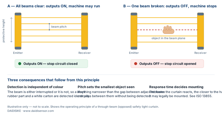
What Does a Safety Light Curtain Do, and When Should You Use One?
A safety light curtain is an electro-sensitive protective device. Its job is to detect a person approaching a hazard early enough for the machine to stop before contact. It suits applications where operators interact with the machine every cycle — feeding a press, loading a molding machine, or passing parts into a robot cell — because there is no gate to open and close.
It is not the right tool everywhere. A light curtain cannot contain ejected parts, splashing coolant, or flying sparks; if those are present you still need a physical barrier, with the curtain guarding the access opening. And if the guarded opening is a door that people walk through occasionally rather than every cycle, a safety door interlock is often simpler and cheaper.
One more distinction matters at the start: safety light curtains are different from measuring light curtains and diffuse area sensors. DAIDISIKE's DD diffuse-reflection area grid, for example, is recommended by its own manual for object and area detection only — not for personnel protection. Always confirm the product family is intended for safety use before designing it into a guard.
For continuous object measurement, use the separate measuring light curtain range. If access is through a physical door, the guard interlock selection guide explains when monitoring or guard locking is needed.
Step 1: What Detection Capability Does Your Hazard Require?
Detection capability is the specified minimum test-object size reliably detected under the documented operating conditions. Beam pitch is the centre-to-centre spacing of optical axes. Both belong on the quotation, but they must not be substituted for one another.
Select detection capability from the reachable body part, access geometry and required separation distance. A stated 14 mm detection capability is a common finger-detection specification; that does not mean a curtain with 14 mm beam pitch detects a 14 mm object. Multi-beam access barriers require their own arrangement and reach-under/over checks.
The current DQC data distinguishes 10/14 mm pitch from 18/22 mm minimum detectable objects. DQT4 lists pitch choices of 7.5/15/30 mm with detection capabilities of 14/21/36 mm respectively. These examples show why the ordering pitch, rated test object and exact configuration must be checked separately; they do not establish the safety rating of a complete installation.
- Required detection capability — record the rated test-object diameter, not a pitch inferred from the model code.
- Protective height and beam arrangement — cover the reachable opening and check access over, under, around and behind it.
- Exact model and output version — retain the relevant manual and safety-performance evidence before treating the device as a personnel safeguard.
- Blanking or other configuration changes — confirm their effect on effective detection capability and re-evaluate the installation.
11 ideal rays; 300 mm between the first and last axes. Actual detection capability depends on the device optics, evaluation and specified test conditions. Obtain the rated test-object size from the exact model document; do not infer finger/hand protection from pitch.
Step 2: What Protective Height Covers the Opening?
Protective height is the vertical span the beams actually cover. It must cover the full zone through which a person can reach the hazard — measure the opening, not the machine.
On DQC-family products the arithmetic is transparent: protective height = (number of beams − 1) × beam pitch, and the model code spells it out as DQC + beam count + "/" + pitch + "-" + protective height. A DQC06/10-50 is six beams at 10 mm pitch giving a 50 mm protective height. Across the DQC range, protective heights run from 50 mm up to 3800 mm with up to 32 beams per unit.
If the opening needs more beams than a standard unit provides, move up a series rather than stacking units: the DQT series extends the same through-beam concept to 72 beams (e.g., DQT72/40-2840 with a 2840 mm protective height), and economy-line options such as the JER and MK series reach protective heights up to 7960 mm at 40 mm pitch with beam counts up to 200.
Step 3: How Far Apart Will the Emitter and Receiver Sit?
Operating range is the distance between the emitter and receiver bars. Standard-range curtains cover most single-machine openings: the DQC series works from 0.3 to 3 m as standard, extendable to 0.3–6 m on request. Measure the real mounting span, then add margin for alignment tolerance and future layout changes.
For wide spans — long conveyor openings, fence lines, large gantries — pick a long-range through-beam series from the start. In the DAIDISIKE catalog the DQA series is positioned exactly there: the long-range variant of the DQC, with the same eight pitch options and the same transparent model-code format, plus dedicated DQA-01/DQA-02 end-mounting brackets for long-span installation.
Also decide early whether a synchronization cable between emitter and receiver is acceptable. Optically synchronized series such as the JER and DQBT need no interconnecting sync cable, which simplifies wiring when the two bars sit on opposite sides of a wide or busy opening.
Step 4: How Close to the Hazard Can You Mount It?
Separation distance depends on the applicable standard edition, approach geometry, detection capability and maximum time for the complete safety function to reach a safe state. S = K × T + an intrusion allowance is useful explanatory arithmetic, not a universal installation formula.
T must account for the sensor, safety logic, final switching elements and machine stopping performance, without double counting delays already included in a measured total. Include deterioration or additional allowances as required by the applicable method; a catalogue sensor response time alone is not the machine stopping time.
ISO 13855:2024 replaced the 2010 edition. The interactive example below is explicitly limited to a legacy perpendicular-approach calculation; it omits other reach, geometry and application checks. A qualified integrator must establish the current applicable method, measured stopping performance and actual detection capability before choosing a mounting position.
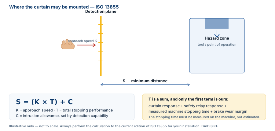
See the ISO 13855:2024 scope and edition information. Give the integrator the detection capability, measured stop-time record, layout and operating modes, not just the curtain's pitch.
Limited to the legacy perpendicular-approach example, d = 14–40 mm. ISO 13855:2024 supersedes the 2010 edition. Other approaches, reach-over/under, whole-body entry, machine-specific rules and current-edition checks are outside this tool. All starting values are hypothetical, not specifications of a DAIDISIKE product.
- T = 215.000 ms = 0.215000 s
- C = 8 × (30 − 14) = 128 mm
- Initial 2000 × T + C = 558.000 mm
- Initial result exceeded 500 mm; historical recalculation uses K = 1600 mm/s
- Applicable historical floor = 500 mm; rounded upward to a whole millimetre.
Do not use this output to approve a new project, certification or machine commissioning. Actual stopping performance must be measured under the appropriate conditions, without double counting delays. A qualified integrator must determine and validate the complete current applicable method.
ISO 13855:2010 — superseded edition · ISO 13855:2024 — current edition scope
How the Curtain Gets Into the Stop Circuit
A sensor state change alone is not a safety function. The purchase specification must identify the safety-related logic and final elements that command and achieve the required safe state, including how faults and restart are managed.
An OSSD-compatible safety relay or controller may evaluate the curtain, but its input mode, test-pulse tolerance and complete application must be validated. A series such as DQS can be supplied with a controller; that does not remove the need to verify the exact controller version, machine interface and safety evidence.
Where required, external-device monitoring checks the final switching elements, while reset and restart interlocking address different tasks. Reset must not itself initiate hazardous motion. If a person can remain behind the detection plane, specify additional presence and restart-prevention measures; never assume clearing a beam proves the space is empty.
For conventional DC input terminology, PNP sourcing outputs pair with sinking inputs, and NPN sinking outputs pair with sourcing inputs. Check the actual input circuit and common connection in the controller manual. The drawing in Step 5 is one DQC single-output variant, not a universal OSSD wiring plan.
Step 5: Which Output Type and Power Supply Do You Need?
Specify the exact output arrangement before ordering: one switched output, independent NPN and PNP outputs, and dual safety OSSD channels are different things. PNP outputs source current into a sinking input; NPN outputs sink current from a sourcing input. Match the selected controller's documented circuit, not a regional convention or a product-family label.
DA31 and DQSRN are catalogue safety-relay options, not automatic compatibility approvals for every curtain. DQSRN supports manual and automatic reset according to the selected model's instructions; EDM capability remains unconfirmed. Determine where the required restart and final-element monitoring functions will be implemented; assess DA31 from its own exact circuit documentation.
On power: DQC-family curtains run natively on DC12/24V. If you are retrofitting an older machine that only has AC available, an external controller option accepts AC110–220V, so you can add guarding without pulling a new low-voltage supply. Wiring is available in 4-core, 5-core, or 6-core configurations depending on series and signal options.
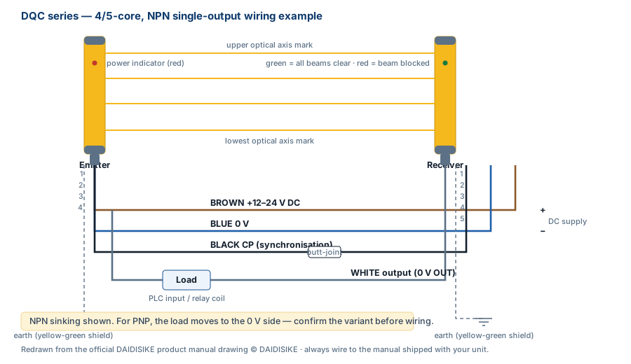
The output-polarity guide helps specify NPN/PNP and NO/NC variants. Rockwell Automation's input/output terminology note confirms the conventional sourcing/sinking pairing; it is not a wiring approval for a DAIDISIKE safety device.
Step 6: Which Housing and Environment Rating Fit Your Machine?
The DQC series publishes IP65, while DQR/DQRF variants have different enclosure specifications, including an IP68 option. An IP number alone does not approve high-pressure or hot washdown, detergents, immersion conditions or coolant compatibility. Submit the actual cleaning process and check the complete installed enclosure, connectors and cable entries.
Space constraints drive a second set of choices. The DQB side-emitting series has a 15 × 30 mm cross-section with beams exiting the narrow side; the DQZ front-emitting series measures 17.2 × 30 mm; and the MK mini economy series has a 25 × 23 mm profile. These slim housings fit inside machine frames and between guides where a full-size bar will not.
Where the first or last beam must sit close to a machine shoulder, check the exact end blind-zone dimension on the DQO drawing rather than reading 'zero blind zone' as literally zero. DCE offers another housing and beam-count range; its suitability for personnel protection still depends on the exact device and safety-function evidence.
Muting and Blanking — and Why They Are Not the Same Thing
Sooner or later something has to pass through the detection plane that is not a person: a pallet on a conveyor, a fixture, a workpiece taller than the opening. Two mechanisms exist for that, they are routinely confused, and confusing them is how a curtain quietly stops protecting anyone.
Blanking permanently ignores specific beams so that a stationary object — a chute, a bracket, a fixture — can occupy the field continuously. Fixed blanking holds one defined zone; floating blanking lets a small object move within the field. In both cases the blanked region no longer detects anything, including a hand, so it must be physically guarded if a body part could occupy it.
Muting is a controlled temporary suspension of a protective function under conditions defined by a validated safety design. Its triggering devices, sequence, timing, permitted modes and fault response must follow the exact system manual and application standard. A material-flow request alone does not make suspension safe.
Do not use blanking or muting to conceal an unresolved reach path. Document why it is needed, its effect on detection and separation distance, and how access is otherwise prevented. Confirm the selected product actually supports the required function.
Commissioning Checks Before the Machine Runs
Treat these as evidence requests for qualified commissioning personnel, not instructions for an untrained buyer to test a running machine. Testing must follow an approved safe procedure, control hazardous energy and keep people out of the hazardous space.
- Obtain the exact-model test-piece procedure and the record of coverage checks throughout the protective field.
- Have qualified personnel validate the complete safe response under a controlled procedure; never use a hand or body as the test object.
- Review the layout for access over, under, around and behind the field, with hazardous energy controlled.
- Compare the measured mounting distance with the approved calculation for the actual detection capability and configuration.
- Retain the maximum stopping-time measurement, test conditions, date and responsible competent person.
- Verify required final-element diagnostics using the manufacturer's approved procedure; do not improvise welded-contact or wiring-fault tests.
- Verify reset, restart prevention, escape and presence measures for the actual access geometry.
- Check reflective surfaces, optical interference, contamination, environment and electrical installation against the exact manual.
Set periodic inspection and stop-time measurement intervals from the machine instructions, risk assessment and applicable requirements. Revalidate after changes to braking, tooling, loads, operating modes or the safety circuit; there is no universal annual interval that replaces these requirements.
What Actually Makes a Curtain Fail in Service
Service problems can arise from alignment, contamination, interference or operation outside the specified conditions. The following are troubleshooting categories, not a ranked list from a published field study.
Check alignment against vibration, mounting movement and the permitted operating span. Review reflective surfaces and other optical devices using the exact manual's separation and interference rules; there is no universal one-metre clearance for every curtain. Correct the cause of intermittent operation rather than widening a blanking zone.
Coolant film and metal dust can attenuate the optical path. Confirm permitted cleaning methods, environmental limits and the device's fault indication; an enclosure IP rating does not establish chemical resistance or optical performance under contamination.
Review fault logs and the actual operating conditions before changing configuration. Nuisance stops are a reason to investigate the installation, not to bypass a protective function.
Which DAIDISIKE Series Should You Start With?
Shortlist only devices whose exact safety evidence and detection capability meet the application requirements. Then use the following catalogue distinctions to discuss space, span and environment; the list is not approval of any family for every safeguarding task.
- DQC — compare the published span, height and pitch options, noting its 18/22 mm detection figures for 10/14 mm pitch and the exact single-output drawing.
- DQA or DQT — investigate wider spans or higher beam counts using the exact order table and safety evidence.
- DQT4 — compare the documented 14/21/36 mm detection capabilities, corresponding to 7.5/15/30 mm pitch.
- DQR / DQRF — discuss wet-environment enclosure options and actual cleaning conditions; IP68 alone is not high-pressure-washdown approval.
- DQB, DQZ or MK — check the available housing space without letting a narrow profile override required safety performance.
- DQO — verify first/last-beam positions and the remaining end blind zone against the actual drawing.
- JER economy series — confirm the exact model's detection and safety evidence before considering cost.
- DA31 or DQSRN — verify input compatibility and required external functions; DQSRN supports manual/automatic reset per its selected-model instructions; EDM remains unconfirmed.
Use the safety light curtain series comparison to turn those constraints into an order shortlist. The Type 2/Type 4 evidence checklist identifies the documents to request before accepting a rating.
For a robot loading cell, the sensor-role application guide explains how opening, gate, floor and process sensors divide the work. Safety edges and safety mats address different contact/presence tasks where justified; none is a universal substitute for the opening safeguard.