
Embodied AI Robots Enter Factories in 2026: How Light Curtains, Guard Locks, Safety Laser Scanners and Displacement Sensors Divide the Work
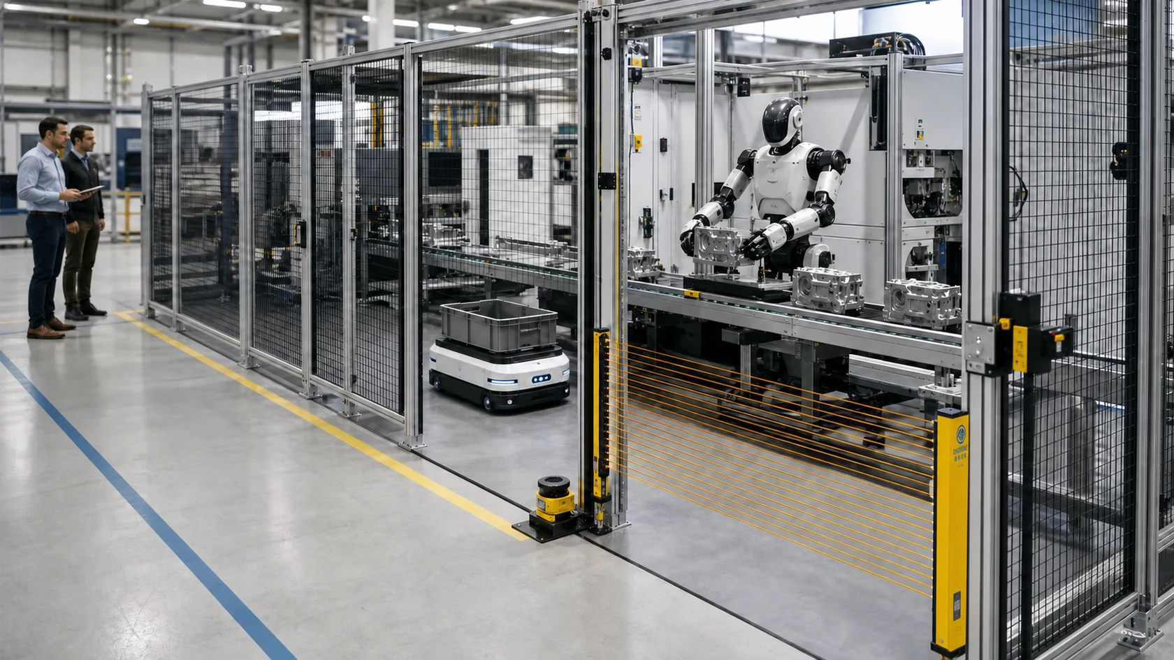
Embodied AI — also called physical AI — is moving from research demonstrations into limited factory pilots. The important word is limited. The International Federation of Robotics says reliability, efficiency, safety and security are among the tests that industrial humanoids still have to pass. A smarter robot may adapt its path or learn a new handling task, but that intelligence does not automatically make the complete robot application safe.
Quick answer: a safety light curtain detects a person crossing a fixed open access point; a guard locking switch controls entry through a physical door and can hold it closed while danger remains; a safety laser scanner monitors a configurable floor area; and a laser displacement sensor measures the workpiece or process. The first three can participate in personnel-protection functions when correctly selected and integrated. The displacement sensor normally belongs to the production and quality loop, not the personnel-safety loop.
That division of work is the central design rule. Do not ask which sensor is most advanced. Ask what hazard must be reduced, how a person can approach it, how long the complete machine takes to reach a safe state, and what diagnostic performance the safety function requires.
Why 2026 Is a Turning Point — but Not Mass Adoption
The IFR's Top 5 Global Robotics Trends for 2026 puts AI-driven autonomy, IT/OT convergence, real-world humanoid testing, safety and security on the same list. That combination matters: the robot is becoming less isolated from production data and more capable of changing its behaviour, while the case for deterministic protection and human oversight becomes stronger rather than weaker.
The installed industrial-robot base is already large. For historical context, IFR's World Robotics 2025 summary records approximately 542,000 new industrial-robot installations in 2024 and an operational stock of about 4.664 million units. Those figures describe industrial robots as a whole — not humanoids — and should not be misread as evidence that embodied robots are already common on every shop floor.
The IFR World Robotics 2026 release, dated 24 September 2026, updates that baseline: around five million industrial robots were operating worldwide in 2025, with more than 600,000 new installations during the year. These are total industrial-robot figures, not a count of humanoid or embodied-AI robots. A large automation market does not establish the maturity or safety of a particular humanoid application.
The more honest signal comes from pilots. BMW Group's production report, currently dated 21 September 2026, describes the AEON pilot at Leipzig and the earlier Figure 02 trial at Spartanburg. Over ten months, Figure 02 handled more than 90,000 components and assisted production of more than 30,000 BMW X3 vehicles. BMW says the trial informed revised safety concepts with additional barriers and partitions. The lesson is practical: physical AI can add flexibility, but deployment still needs engineered safeguarding. This is BMW's first-party pilot report, not a DAIDISIKE customer case or evidence that BMW uses DAIDISIKE devices.
IFR's separate Humanoid Robots: Vision and Reality paper is equally careful. It says the timing of mass adoption is uncertain and expects humanoids to complement existing robots rather than replace them. This article therefore treats 2026 as a transition from prototype to controlled production use — not as permission to remove fences or trust AI perception as a safety function.
The First Separation: AI Control, Safety Control and Process Measurement
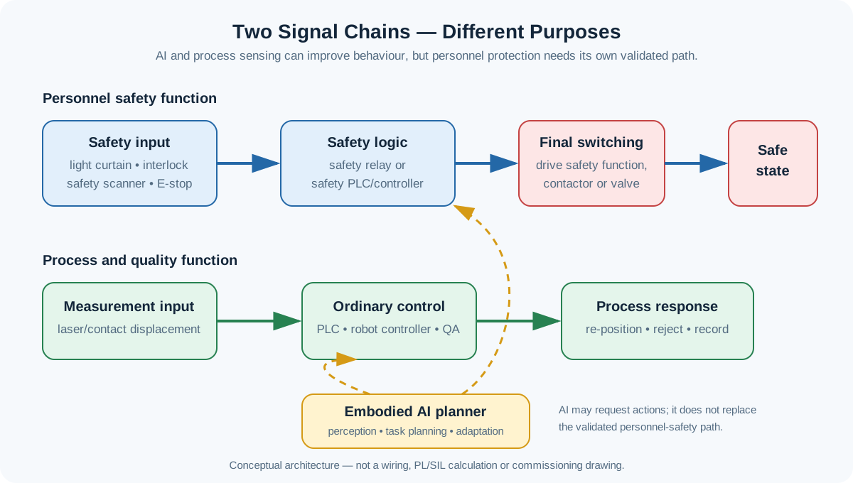
An embodied robot normally contains several perception and control layers. Cameras, ordinary LiDAR, force estimation and a vision-language-action model help it understand the scene and plan an action. Servo loops execute the movement. Process sensors confirm that the right part is present or that a dimension is within tolerance. Separately, safety-related inputs, logic and final switching elements must bring the hazardous application to a defined safe state when required.
Google DeepMind's Gemini Robotics description makes a similar architectural distinction: high-level embodied reasoning can connect to low-level, embodiment-specific safety-critical controllers. In a factory risk assessment, that is not merely a software preference. The safety function needs defined behaviour, diagnostics, response time and validation. A probabilistic AI model that can re-plan a task should not be treated as the sole channel that decides whether a person is protected.
The safety chain starts at a safety-related input and continues through the logic and the elements that actually remove or control hazardous energy. A normal PLC status bit is useful for diagnostics and production management, but it does not become a safety output because the AI reads it. Likewise, a displacement measurement can make the process more accurate without contributing any risk reduction for a person.
Four Devices, Four Different Jobs
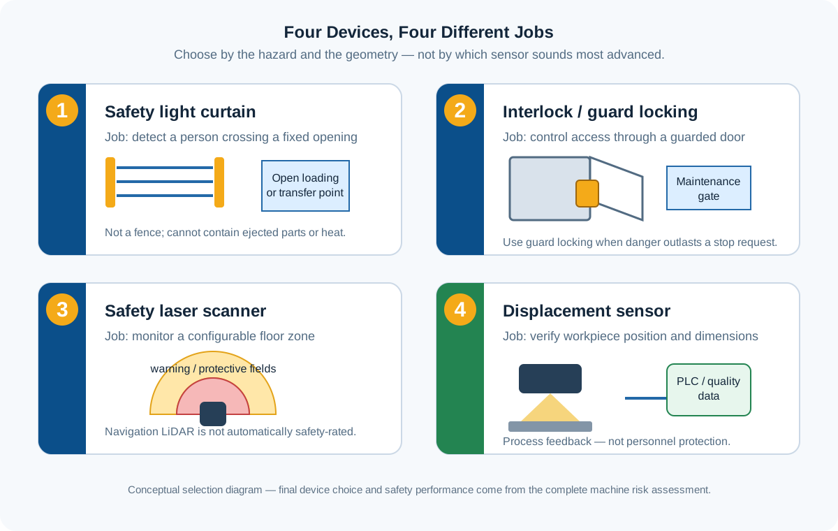
The four product families in this article overlap visually — all of them sense something — but they answer different engineering questions. The table is the shortest useful comparison.
| Device | Primary question | Typical location | What it does not replace |
|---|---|---|---|
| Safety light curtain | Did a person cross this fixed open plane? | Loading opening, transfer point, operator access | A physical guard against ejected parts, heat, radiation or a person remaining hidden inside |
| Interlock / guard locking switch | Is the guard closed, and must it stay locked until danger ends? | Maintenance door or fenced-cell access gate | Presence detection across an open floor or inside the cell |
| Safety laser scanner | Is a person entering or present in this two-dimensional floor field? | Open robot station, approach aisle, AGV/AMR perimeter | Finger/hand-resolution protection or containment of process hazards |
| Displacement sensor | Is the part at the expected height, position or dimension? | Gripper station, fixture, inspection point, conveyor | A certified personnel-protection sensor or safety-rated stop chain |
A Practical Selection Worksheet for the Integrator
Start with the task and access geometry. The following questions keep a project from buying several plausible devices and discovering during commissioning that none covers the actual route into danger.
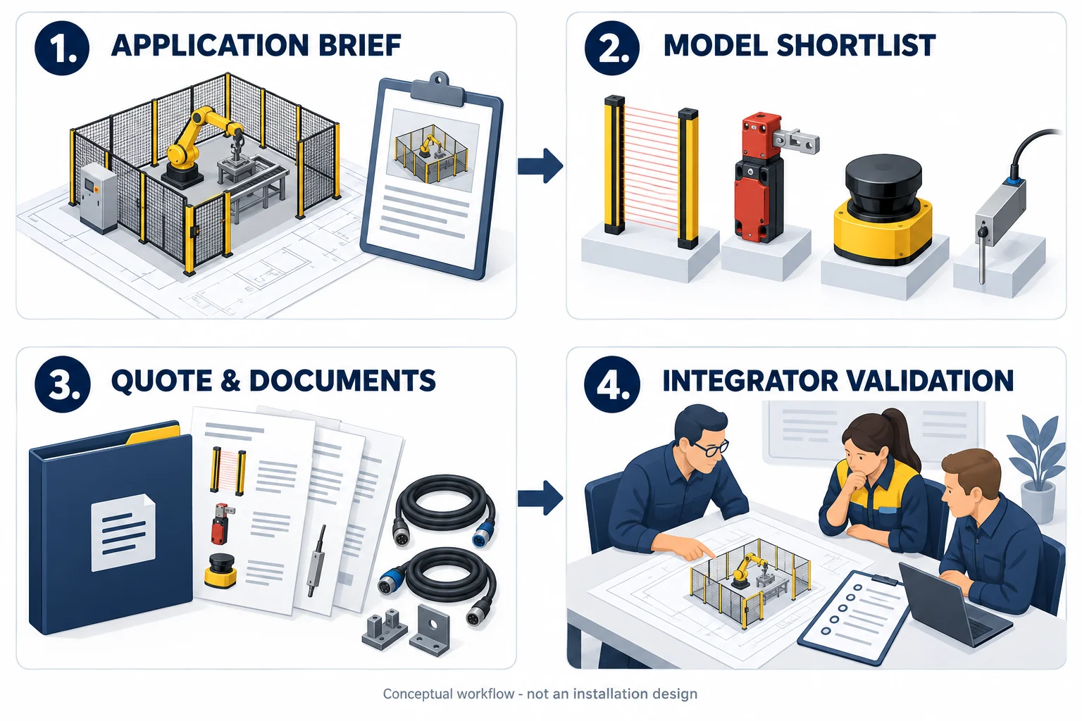
For a quotation, separate the safety-device shortlist from the process-measurement bill of materials. Include each exact output version, cable/connector, actuator or mounting accessory and requested document revision; the application layout alone does not identify a complete order code.
Use this as a requirements-to-quotation workflow: record the application, shortlist a device family, confirm the orderable version and documentation, then have the qualified machine integrator design and validate the complete application. The worksheet and worked example are hypothetical engineering aids, not a customer installation, witnessed demonstration or validated safety design. Mark unknown inputs as unresolved rather than choosing a convenient value.
The public download centre contains the existing reference documents linked below. A family brochure or shared manual is not proof that every output, firmware version or accessory has the same scope. ST27 and JNS-Q currently have no publicly listed PDF in this catalogue: request the exact model's current manual, drawings and applicable evidence before final selection, and do not treat the product page alone as a commissioning document.
- Application record: provide the cell layout, each human and material access route, robot/tooling/payload envelope, operating and recovery modes, required safe state, measured maximum stopping time, environment and destination market. Identify the person responsible for the risk assessment and validation.
- Version and quantity: list the proposed family, exact order code where confirmed, quantity and separate safety or process role. Record the applicable detection capability, field or measurement range, output/interface, supply and configurable firmware/software revision. If an order code or interface is not verified, label it provisional; do not treat a family name as a complete bill of materials.
- Accessories and cables: confirm the matching actuator, mounting brackets, cable length, connector and pinout, cable routing and any required configuration lead or tool. Ask which items are included and which are quoted separately. Confirm compatibility with the selected safety logic or ordinary process controller; similar connectors do not prove electrical compatibility.
- Opening and door references: use the existing DQO user manual, DQO technical data sheet, DX-D6 data sheet and DX-R1 manual. Match the document revision, output version, actuator and release/locking arrangement to the proposed order.
- Control and process references: the DA31 manual and DDK-G data sheet support their respective logic and measurement shortlists. The shared DLD-50D reference manual is for the stated navigation/measuring variants, not personnel protection or proof of identical specifications across other LiDAR families. Retain the revision and applicable model for each supplied document.
- Open-items register: identify missing ST27/JNS-Q documents, exact-model safety evidence, required PLr/SIL, stopping-time results, separation-distance calculation, reset and restart logic, field-switching needs and any unresolved accessory or wiring question. DAIDISIKE can help clarify catalogue options; the qualified integrator must resolve and validate the application safety functions before commissioning. A quotation or concept demonstration is not that validation.
| Question | Likely device family | What must still be verified |
|---|---|---|
| Must people frequently cross a fixed open access point? | Safety light curtain | Detection capability, stop time, separation distance, bypass and restart prevention |
| Is access through a physical gate? | Safety interlock | Coding/defeat resistance, safe stop and prevention of unexpected restart |
| Does dangerous motion continue after the stop request? | Guard locking switch | Lock strategy, release condition, escape/manual release and residual energy |
| Is the approach an open or variable floor area? | Safety laser scanner | Protective field, resolution, occlusion, field switching and measured braking/stopping distance |
| Does the robot need part height, gap or position feedback? | Laser/contact displacement sensor | Target surface, measuring range, resolution, response time and process interface |
| Can people enter and remain hidden inside the safeguarded space? | Additional presence / trapped-person / reset measures | Whole-space coverage, escape, lockout and restart procedure |
| Can the process eject, burn, irradiate or spray? | Physical guard or enclosure plus interlocking | Containment and the applicable process-specific standard |
1. Safety Light Curtains: A Detection Plane Across an Open Access Point
A safety light curtain is strongest where a production opening must remain physically open: a robot loading station, a part-transfer window or an operator interface. The emitter and receiver form a defined plane. When the specified test object interrupts the beams, the safety outputs change state and the downstream safety-related control system requests a safe stop.
For a compact transfer opening, the DQO product page is a catalogue example to investigate. It lists beam-pitch, height and housing data, but the exact output arrangement, remaining end blind zone, detection capability and safety evidence must be reconciled with the ordered version. A 'zero blind-zone' name and a family-level Type claim are not a machine-safety approval.
The light curtain's response time is only one part of the separation-distance calculation. The integrator must include the safety logic, drive or valve response, robot and tooling stopping performance, and the applicable intrusion allowance. The maximum stopping time of the complete application must be measured and validated — not copied from a robot brochure.
A curtain also cannot solve every access problem. If a person can pass through the plane and stand behind it, the design must address presence inside the safeguarded space, blind zones, reset location and prevention of unexpected restart. If the robot process can eject a part, produce welding radiation, heat or hazardous fluid, a physical enclosure remains necessary because an optical field contains nothing.
Turn the opening requirements into a purchase shortlist with the light-curtain selection guide, keeping rated detection capability separate from beam pitch and confirming the evidence for the exact output version.
- Use it for a frequently crossed, fixed opening where hazardous motion can stop before the person reaches the hazard.
- Choose detection capability according to the reachable body part; beam pitch is not the same number as minimum detectable object size.
- Measure the full stop time and position the field under ISO 13855:2024 and the applicable machine standard.
- Design against reach-over, reach-under, step-through and a person remaining undetected inside the cell.
2. Interlocks and Guard Locking: Control the Door, Not the Floor
A movable guard creates a different question. A safety interlock tells the safety-related control system whether the door is closed. Opening it must initiate the required safe response and prevent hazardous restart while the door remains open. Guard locking adds a second function: it physically holds the door closed until the risk from run-down, stored energy, gravity or another residual hazard has ended.
The distinction matters in robot cells. If hazardous movement stops before a person can reach it, an interlocked guard may be sufficient after risk assessment. If the robot, spindle, turntable or heavy load continues moving after a stop request, opening the door immediately can still expose the person. That is when guard locking, safe release logic and an emergency/manual release strategy require careful design under ISO 14119:2024.
The DX-D6 guard locking safety-door switch is the relevant DAIDISIKE model for the second case. Published product data states a 2000 N holding force, redundant monitoring outputs and two lock strategies: mechanical lock with solenoid release, or solenoid lock with mechanical release. The risk assessment must choose the appropriate strategy; power-to-lock and power-to-release are not interchangeable assumptions.
Where the requirement is only non-contact coded door-position monitoring and no locking force is needed, the DX-R1 non-contact safety switch is a different product class. Calling every door sensor a 'safety lock' hides a real design decision. Neither product detects a person who is already standing elsewhere inside the enclosure.
Before ordering, use the guard interlock and locking selection guide to specify the lock strategy, actuator, output/connector and escape provisions. A door sensor does not replace measures for a person remaining elsewhere inside the cell.
| Access condition | Likely function | Design question |
|---|---|---|
| Hazard reaches a safe state before access is possible | Guard interlocking | Does opening reliably request the safe state and prevent restart? |
| Hazard remains after the stop request | Guard locking plus interlocking | When may the door be released, and what happens on loss of power? |
| Person can be trapped or hidden inside | Additional presence / escape / reset measures | How is unexpected restart prevented after entry? |
3. Safety Laser Scanners: Flexible Protective Fields on the Floor
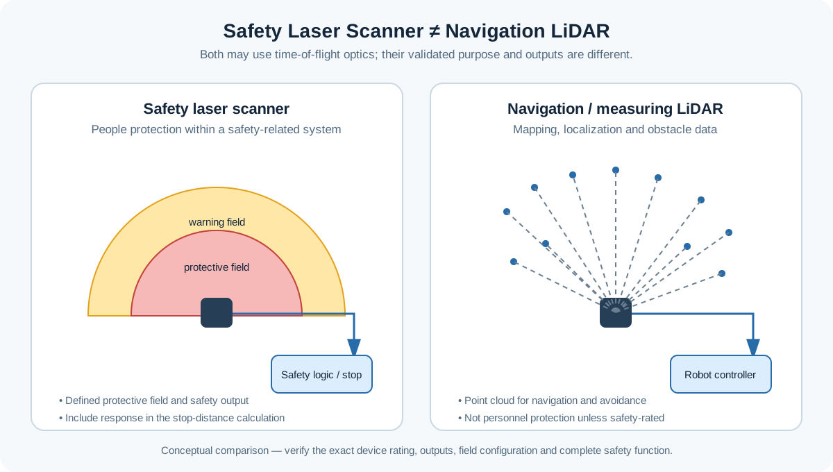
A safety laser scanner is the natural choice when the protected geometry is an area rather than a line. It repeatedly measures the position of objects across a two-dimensional scan plane and compares them with configured fields. On an open robot station this can support approach detection or presence sensing; on a mobile platform it can support speed-dependent protective fields, subject to the applicable mobile-robot standard and verified braking performance.
The ST27 safety laser scanner is the safety-rated owner in this catalogue. Its published data states Type 3 under IEC 61496, SIL 2, Category 3 / PL d, a 276-degree scan, 3 m or 5 m protective-field variants at low target remission, 70 mm object resolution at the maximum protective radius, and variants with PNP OSSD outputs. These numbers are useful inputs; they do not by themselves validate the complete robot application.
Protective and warning fields must not be confused. The ST27 warning range is useful for alerts or ordinary process actions, but its product data explicitly says the warning and measuring ranges are not safety functions. A person entering the validated protective field is what must produce the defined safety response. Field switching, reference boundaries, mounting height, occlusion, worst-case clothing remission and the complete stop distance all require application-level verification.
The same distinction applies to the robot's own LiDAR. The DLD-50D navigation and mapping LiDAR produces Ethernet point-cloud data for localization and obstacle mapping. It is useful perception equipment, but it has no published personnel-safety rating and must not be substituted for ST27 in a safety function. Shared optical vocabulary does not create shared functional-safety capability.
The LiDAR selection guide compares ordinary interfaces and target conditions with the separate safety-scanner decision. Keep protective, warning and measurement distances in distinct quotation fields.
4. Displacement Sensors: Process Feedback, Not Personnel Protection
The fourth device is deliberately different. A laser displacement sensor measures the workpiece rather than the person. In an embodied-robot station it can confirm that a bin, casting, battery module or fixture is at the expected height before the robot commits to a grasp. It can measure thickness, gap, runout, step height or assembly seating and send a continuous value to the PLC, robot controller or quality system.
The DDK-G laser displacement sensor is a non-contact example with five reference-distance grades from 30 to 250 mm, resolution beginning at 2 micrometres under the published test conditions, and analog or RS485 variants. That makes it useful for robot positioning and in-line quality checks. It does not make DDK-G a personnel-protection device.
Where contact measurement suits the target, the JNS-Q contact displacement sensor is an alternative to investigate. Confirm the exact probe's stroke, resolution, accuracy and interface rather than treating family figures as interchangeable; the confirmed Q120 configuration has a 12.7 mm stroke and ±2 micrometre accuracy. It remains a process-measurement device, not a personnel safeguard.
This boundary is explicitly consistent with IEC 61496-3:2025, whose scope excludes devices that perform only a single one-dimensional spot-like distance measurement. The safety laser scanner protects people; the displacement sensor verifies the process. Both may measure distance, but they do not perform the same function.
- Use laser displacement for non-contact height, gap, thickness, alignment or runout measurement.
- Use contact gauging when surface reflectivity makes an optical result difficult and physical contact is acceptable.
- Send measurement values to ordinary control or quality systems; do not count them as personnel risk reduction without a safety-rated product and validated safety function.
- Define the target material, surface, reference distance, required resolution, cycle time and interface before choosing the model.
Worked Example: An Embodied Robot Loads a Machine
This is a hypothetical workflow used to explain the allocation of functions. It is not a DAIDISIKE customer case, a tested installation or a demonstration that any specific device combination achieves the required safety performance. The dimensions and events in this example are illustrative, not acceptance criteria.
Consider a humanoid-style or mobile manipulator loading cast components into a fixed machining station. The robot receives a production order, identifies the part, picks it and presents it to a fixture. The useful design is not 'one smart sensor'. It is a set of boundaries aligned to how people and material move.
At the transfer opening, a safety light curtain detects a person crossing the fixed plane. At the maintenance gate, a guard-locking switch prevents release until the robot and connected machine have reached the safe state defined by the risk assessment. A safety laser scanner covers an open approach or a floor area where a person could enter around the transfer path. A displacement sensor checks the raw part height and seating position before machining begins.
The AI can decide which component to pick and can re-plan after a failed grasp. The displacement sensor can tell it that the component sits 1.2 mm too high. Neither signal is the personnel-protection decision. If a person breaks the light curtain, opens the gate or enters the protective scanner field, the independent safety-related control system must produce the specified stop regardless of what the AI intended to do next.
- Production state: AI plans the move; displacement sensing verifies the part and fixture.
- Material transfer: the opening safeguard is designed so valid material flow does not create an unsafe bypass.
- Human intrusion: the appropriate safety sensor changes state and the safety logic commands the defined safe response.
- Maintenance entry: the door is released only under the validated conditions, and restart requires a deliberate procedure with a clear view of the safeguarded space.
- Recovery after a fault: the operator uses the documented safe mode and enabling/control measures; the AI does not improvise a restart.
What the Safety Chain Must Do After Detection
A protective sensor does not stop a robot by itself. Its outputs enter safety-related logic, which evaluates the channels and commands the final elements that control hazardous energy. Those elements may be drive safety functions, redundant contactors, monitored valves or another architecture justified by the required performance level. The complete function — input, logic and output — is what ISO 13849-1:2023 asks the integrator to design and evaluate.
For a compact fixed application, the DA31 safety relay module is a relevant logic example. Its published data includes dual-channel PNP/NPN input modes for an emergency stop, light curtain, door interlock or two-hand control, plus forcibly guided relay contacts and a separate status output. The status output can inform an ordinary PLC without making the PLC the safety decision maker.
A scanner application with multiple field sets, safe speed selection or mode-dependent logic may require a suitable safety controller or safety PLC rather than a simple relay. The correct architecture comes from the safety-requirements specification. Do not add unverified reset, EDM or field-switching functions to a product simply because the overall application needs them.
For the relay choice, the documented safety-relay comparison separates available input and contact arrangements. DQSRN supports manual and automatic reset per its selected-model instructions; EDM capability remains unconfirmed. Allocate and validate the required restart and final-element monitoring functions using the exact device and circuit documentation.
| Stage | Engineering question | Evidence to retain |
|---|---|---|
| Input | Does the selected device detect the defined person, door or field condition? | Exact model, type/rating, configuration, response time and test record |
| Logic | Does the safety relay/controller diagnose faults and execute the required reset/mode logic? | Safety-requirements specification, wiring, configuration and validation results |
| Output | Does the drive, contactor or valve reach and maintain the defined safe state? | Measured stopping performance and final-element diagnostics |
| Application | Can a person reach, bypass, remain inside or restart unexpectedly? | Risk assessment, layout, separation-distance calculation and periodic inspection plan |
Standards Map: Which Document Answers Which Question?
No standard number is a substitute for the exact text or for local legal requirements. This map only shows where an integrator normally starts.
| Standard | Primary scope in this design |
|---|---|
| ISO 12100:2010 | Hazard identification, risk assessment and the risk-reduction process for the complete machine |
| ISO 10218-1:2025 | Safety requirements for the industrial robot as partly completed machinery |
| ISO 10218-2:2025 | Integration, commissioning, operation and maintenance of industrial robot applications and cells |
| ISO 13849-1:2023 | Design and integration of the safety-related parts of the control system |
| ISO 13855:2024 | Positioning and dimensioning safeguards relative to human approach |
| IEC 61496-2:2020 | Active opto-electronic protective devices such as safety light curtains |
| IEC 61496-3:2025 | Diffuse-reflection electro-sensitive protective devices such as safety laser scanners |
| ISO 14119:2024 | Selection and application of guard interlocks and measures to minimize defeat |
Common Design Mistakes to Reject Before Commissioning
Most serious failures in a layered robot cell are category errors: a useful function is mistaken for a safety function, or one boundary is expected to cover a different geometry.
- Treating the robot's cameras or navigation LiDAR as a certified protective device because the robot can avoid obstacles during a demonstration.
- Using a scanner warning field as though it were the validated protective field that commands the safe response.
- Counting a displacement sensor's part-presence output as personnel risk reduction.
- Specifying a non-locking interlock where residual hazardous motion continues after the stop request.
- Installing a light curtain at a convenient mechanical position without measuring the complete maximum stopping time.
- Ignoring a person who can step through the opening, move behind the detection plane and remain inside the cell.
- Routing a safety sensor through an ordinary PLC task and assuming duplicated software tags create safety integrity.
- Using product family claims instead of the exact ordered model's manual, certificate scope and configuration record.
- Allowing an automatic reset or AI-initiated restart when the safeguarded space cannot be fully observed and verified clear.
Evidence and Scope of This 2026 Review
This article uses first-party industry reporting and the current published standard editions rather than predictions copied from general media. The main references are listed here so an integrator can verify the scope and publication status.
- IFR — Top 5 Global Robotics Trends 2026: AI/autonomy, humanoid reliability, safety and security trends.
- IFR — World Robotics 2025: historical 2024 global industrial-robot installation and operational-stock figures.
- IFR — Five Million Robots now Operate in Factories Globally, 24 September 2026: World Robotics 2026 reporting on 2025 industrial-robot stock and installations, not humanoid deployment totals.
- BMW Group — humanoid production pilot report, 21 September 2026 as currently displayed: Leipzig's AEON pilot, Spartanburg's earlier Figure 02 trial and revised barrier concepts. External industry context, not a DAIDISIKE supply reference.
- Google DeepMind — Gemini Robotics: embodied reasoning and layered safety from high-level semantics to low-level controllers.
- ISO 10218-1:2025 and ISO 10218-2:2025: industrial robot and integrated robot-application safety scopes.
- ISO 13849-1:2023, ISO 13855:2024 and ISO 14119:2024: safety-related controls, safeguard positioning and guard interlocking.
- IEC 61496-2:2020 and IEC 61496-3:2025: safety light-curtain and diffuse-reflection protective-device scopes.
Frequently Asked Questions
Can an embodied AI robot's own cameras or LiDAR replace a safety scanner?
When should a robot cell use a light curtain instead of a safety laser scanner?
What is the difference between a safety interlock and guard locking?
Can a laser displacement sensor be used for machine safety?
Does installing these four devices make a robot cell compliant with ISO 10218?
Do collaborative or humanoid robots still need guarding?
Where does a safety relay fit in an embodied robot cell?
What information should I send when requesting sensor selection help?
Products Referenced in This Article
- DQO Zero Blind-zone Safety Light Curtain — Compact 30x28mm safety light curtain with a near-zero end blind zone: catalog dimensions place the first and last beams only 6.75mm from the housing tips, across 10/20/30mm beam pitch and 4-72 beam axes. NPN/PNP transistor output with dual OSSD channels, IP65, response time <=15ms. Designed to the Type 4 architecture of IEC 61496-1/2 and Category 4 (PLd) of EN ISO 13849-1:2015.
- DX-D6 Guard Locking Safety-Door Switch — Guard locking safety-door switch: 2000 N holding force, redundant dual outputs, RFID-coded actuators.
- DX-R1 Non-contact Safety Switch (RFID Coded) — Non-contact RFID-coded safety switch, dual-channel PLe/Type 4 output, 0-10mm switch-on, cascadable, 8 NPN/PNP models.
- ST27 Series Safety Laser Scanner (Type 3 ESPE, 3 m / 5 m Protective · 20 m Warning · 60 m Measuring) — A Type 3 safety laser scanner for machine builders and AGV/AMR integrators who must stop a machine when a person enters a hazardous area — it replaces fences and multiple light curtains with one 276° horizontal protective field of 3 m or 5 m, wired straight to a safety relay or safety PLC by OSSD.
- DLD-50D 2D TOF LiDAR for Navigation & Mapping (50 m) — 50 m-range 2D TOF LiDAR for mobile robot navigation and mapping — ±20 mm repeatability, 280° FoV, Ethernet output.
- DDK-G Laser Displacement Sensor 30-250 mm — Five reference-distance grades, 20 model codes, and a choice of 4-20 mA, 0-10 V or RS485. Resolution starts at 2 um on G30 under the published test conditions; select by measuring window, target and required output.
- JNS-Q Contact Displacement Grating Sensor — Digital, RS-485-networkable contact displacement sensor with resolution down to 0.2 micron for inline dimensional inspection.
- DA31 Emergency-Stop Safety Relay Module — Ultra-slim 22.6 mm Category 4/PL e/SIL 3 safety relay with dual-channel PNP/NPN input and a solid-state status output.