
DX-D6 Guard Locking Safety-Door Switch
Guard locking safety-door switch: 2000 N holding force, redundant dual outputs, RFID-coded actuators.
▶ Watch it in action: Safety Light Curtain + Guard-Locking Door Switch Interlock — Wiring Demo
 🔍 Click to enlarge · 1/11
Technical Specifications
| Output type | N = dual NPN output / P = dual PNP output (independent redundant dual outputs) |
|---|---|
| Coding | S = universal coded / D = uniquely coded |
| Locking method | C = mechanical lock / solenoid release / D = solenoid lock / mechanical release |
| Function level | R = standard type / H = high-function type, adding EDM and Reset per the published function table |
| Connection | A = direct leads (3 m default) / B = M12 male connector; match standard 8-pin / high-function 12-pin cable to exact version |
| Construction | Nylon / zinc alloy / stainless steel per technical sheet; integrated guard locking + monitoring |
| Holding force | 2000 N |
| Cross-section | 30×30mm |
| Cascading | Up to 20 devices per technical sheet; exact wiring, response and controller compatibility require verification |
| Supply / protection | DC 24 V ±15%; rated power 4.6 W (no load); IP65 |
| Operating environment | -20 to +55 °C, no freezing; 5-95% RH per technical sheet |
| Output current limits | OSSD control output: ≤200 mA; non-safety AUX output: 50 mA; verify exact circuit and load |
Overview
DX-D6 is an electronic guard-locking interlock switch for machine fences and access doors. Choose C-type mechanical locking with solenoid release or D-type solenoid locking with mechanical release, then match the output, function level, actuator and connection to the machine's safety design. The switch reports door/lock state; the safety controller and complete circuit must establish safe release and restart conditions.
The published range contains 32 switch models, a rated holding force of 2000 N, dual NPN or dual PNP outputs and a compact 30×30 mm body cross-section. The technical sheet lists nylon, zinc alloy and stainless steel construction. For CNC guards, robot-cell doors or line fencing, quote the complete set: switch, matching DX-K9 actuator, door-motion bracket, cable and required release arrangement.
Choose the Exact DX-D6 Configuration
Read the complete code as DX-D6-[C/D][R/H]-[S/D][N/P]-[A/B]. These fields describe different choices; a shared DX-D6 family name does not make every wiring diagram or accessory interchangeable.
| Code field | Published choice | Confirm before ordering |
|---|---|---|
| C / D - locking | C: mechanical lock, solenoid release. D: solenoid lock, mechanical release. | Required behaviour during power loss and hazardous run-down; emergency/escape and maintenance release provisions. |
| R / H - function | R: standard. H: high-function, adding EDM and Reset in the published function table. | Exact R/H wiring and how reset and external-device monitoring are implemented in the complete circuit. |
| S / D - coding | S: universal-coded DX-K9S actuator. D: unique-coded DX-K9D actuator. | Pairing/replacement procedure and declared coding level; S/D alone is not an ISO 14119 coding-level statement. |
| N / P - output | N: dual NPN. P: dual PNP. | Compatible safety-controller input, diagnostics and circuit; not a choice based only on the destination country. |
| A / B - connection | A: direct lead, default 3 m. B: M12 male connector. | Standard 8-pin versus high-function 12-pin cable, exact pin-out, cable length and what is included in the quotation. |
Start with the guard-lock selection guide if the locking strategy is undecided. If only door-position monitoring is needed, compare the existing safety-door switch range instead of specifying a lock by default.
Order the Switch, Actuator, Bracket and Cable as a Matched Set
The DX-K9 actuator belongs to DX-D6. It is a different system from the mechanical DX-K1–K8 operation keys used with the DX-W and DX-D2/D3 families. Match the switch's S/D coding to DX-K9S/DX-K9D, and request the documented pairing procedure for a unique-coded replacement.
| Item | Documented choice | Purchase-order check |
|---|---|---|
| Switch body | One of the 32 complete DX-D6 model codes below | State C/D, R/H, S/D, N/P and A/B; do not order only 'DX-D6'. |
| Actuator | DX-K9S universal-coded / DX-K9D unique-coded | Match the switch coding and confirm actuator inclusion and pairing. |
| Hinged-door bracket | DX-K9-L: left-opening. DX-K9-L1: right-opening. | Confirm the opening direction against the accessory drawing and actual mounting view. |
| Sliding-door bracket | DX-K9-T1: left-opening. DX-K9-T2: right-opening. | Confirm travel, approach, stops, alignment and the actual mounting view. |
| Cable | M12 standard 8-pin / high-function 12-pin; default length 3 m | Match R/H and A/B, verify the model-specific pin-out and quote any different length. |
| Release and installation | Release arrangement appropriate to the machine and exact model | Confirm full-body access, escape/maintenance needs, mounting hardware and responsibility for final validation. |
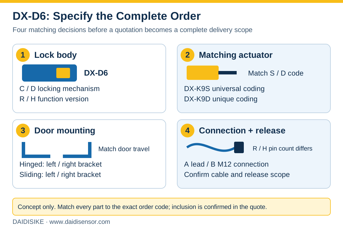
Check the accessory and wiring pages in the DX-D6 English technical data sheet. Send the complete switch code, quantity, door motion/opening direction, actuator and cable requirements through the product quotation form. A quotation is not approval of the complete machine-safety function.
DX-D6 Guard Locking and Monitoring Sequence
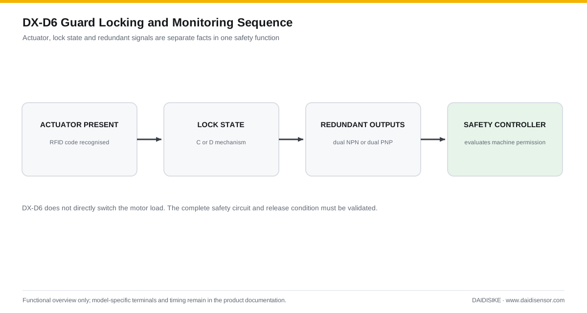
DX-D6 performs two related jobs: it holds the guard closed and reports redundant state signals to the safety controller. The RFID actuator identifies that the door has reached the switch; the locking mechanism secures it; the controller evaluates the switch outputs before permitting hazardous motion. On a stop request, the machine must reach the release condition before the lock is released.
This is a functional overview, not a timing or terminal diagram. Release logic, controller evaluation and the complete stop circuit must be validated from the exact C/D, R/H, S/D, N/P and A/B model ordered.
Power-to-Release vs Power-to-Lock DX-D6
| DX-D6 lock code | Published mechanism | Loss-of-power behaviour to assess |
|---|---|---|
| C type | mechanical lock / solenoid release | power is required to release the guard |
| D type | solenoid lock / mechanical release | loss of power releases the electromagnetic lock |
The selection is a risk decision, not a convenience preference. If hazardous motion or stored energy remains after power loss, the guard may need to remain locked; if emergency release is the dominant requirement, the safe behaviour may differ. Compare the other safety door switches and guard locks before fixing the architecture.
Features & Benefits
Guard locking with integrated monitoring
The device adds a physical locking function to door/lock-state monitoring. The complete machine control must determine when hazardous motion has stopped and when unlocking or restart is permitted; the switch alone does not establish those conditions.
2000 N holding force
The technical sheet gives lock holding force Fzh ≥2000 N. Suitability still depends on door forces, actuator, mounting, fasteners and guard construction; this figure is not blanket approval for every guard.
Two locking logics for two risk profiles
Available as C-type (mechanical lock / solenoid release, power-to-release — stays locked on power loss) or D-type (solenoid lock / mechanical release, power-to-lock — releases automatically on power loss), so the correct locking behavior can be matched to the machine's risk assessment.
Redundant dual-channel outputs
Choose the dual NPN or dual PNP version for the documented compatible safety input. Achieved fault detection and safety performance depend on the complete wiring, diagnostics and controller evaluation, not redundancy alone.
Universal or uniquely coded actuators
Choose a universal-coded actuator (DX-K9S) for easy commissioning and part interchange, or a uniquely coded actuator (DX-K9D) that is only accepted by its paired switch, raising resistance to defeat by a spare actuator.
Compact 30×30 mm cross-section
Nylon, zinc alloy and stainless steel are listed in the technical sheet. Check mounting dimensions, door stops and actuator alignment against the actual frame; a compact cross-section does not guarantee adapter-free installation.
Cascadable to reduce controller I/O
The published cascade limit is up to 20 devices. Use the approved exact circuit and assess total response time, diagnostics and fault masking before assigning several access doors to a shared safety input.
Full mounting bracket range for hinged and sliding doors
The DX-K9 actuator range is supported by rotary brackets (DX-K9-L / DX-K9-L1, for hinged doors) and slide-actuated brackets (DX-K9-T1 / DX-K9-T2, for sliding doors), in both left- and right-opening variants.
32-variant model range for exact-fit selection
R is standard; H adds EDM and Reset in the function table. Choose A direct leads or B M12 connector, and match the standard 8-pin or high-function 12-pin cable to the ordered version. The 32 complete switch codes remain listed below.
Applications
Models & Ordering Information
DX-D6 Switch Models (32 variants)
Actuators
Mounting Brackets
PDF & 3D CAD Downloads
Browse all downloadsDX-D6 Technical Data Sheet (English)
15 pages covering model selection, technical data, accessories, dimensions, indicator status and wiring diagrams. Match the diagrams to the exact model ordered.
Confirm the document and CAD file match the exact ordered version before installation or mechanical design. Contact us if your model is not listed.
How to Select
- Choose C-type (mechanical lock / solenoid release) if hazardous energy remains after power-off and the door must stay locked when power is removed.
- Choose D-type (solenoid lock / mechanical release) only where the risk assessment permits loss of electromagnetic holding action on power loss. Confirm the safe release conditions and any required escape or maintenance-release provisions; D-type is not a universal rescue or evacuation solution.
- Choose R (standard) or H (high-function); the published function table adds EDM and Reset on H. Confirm the exact circuit and reset strategy rather than treating H as universally required.
- Choose S (universal coded) actuators for easier commissioning and part interchange, or D (uniquely coded) actuators where tamper resistance against a spare actuator is required.
- Choose N (dual NPN) or P (dual PNP) outputs to match the safety controller or PLC input type.
- Choose A (direct leads, 3 m default) or B (M12 connector), then confirm cable length, the standard 8-pin or high-function 12-pin version, pin-out and cable inclusion.
- For hinged doors, DX-K9-L is the published left-opening bracket and DX-K9-L1 the right-opening bracket; for sliding doors, DX-K9-T1 is left-opening and DX-K9-T2 right-opening. Confirm direction from the installation view.
- The model number combines all five selection dimensions: DX-D6-[C/D][R/H]-[S/D][N/P]-[A/B], covering 32 fully enumerated part numbers.
📘 Need the full method? How to Choose a Safety Door Switch / Interlock
When NOT to specify the DX-D6 — and what to use instead
The application only needs to detect door open/closed status, with no requirement to physically hold the guard shut.
Why not: DX-D6's core function -- and added cost -- is guard locking; a monitoring-only switch is a simpler fit when no coast-down or stored-energy hazard exists after the stop command.
Use instead: DX-C1, DX-D2/DX-D3, or DX-R1 position-monitoring switches
Risk assessment calculates that the guard door may be forced with more than the rated 2000 N holding force.
Why not: 2000 N is DX-D6's rated holding force; forces above this are outside the device's published capability.
Use instead: No higher-holding-force guard-locking switch is currently cataloged; consult the factory on supplementary mechanical restraint before relying on DX-D6 alone
The panel is wired for conventional relay-based safety circuits and does not need RFID-coded actuators or NPN/PNP transistor outputs.
Why not: DX-D6 requires a DX-K9S/DX-K9D RFID actuator and outputs dual NPN or PNP signals rather than plain NC/NO contacts.
Use instead: DX-W2, DX-W3, or DX-W5 mechanical-contact guard-locking switches
The mounting drawing, actuator approach or door movement cannot be accommodated on the actual frame.
Why not: A 30x30 mm cross-section does not establish fit by itself. Stops, alignment, brackets and the actuator path must work as an assembly.
Use instead: Review a suitable bracket/adapter or compare the existing safety-door-lock range after checking the actual installation dimensions
The project requires a published PFHd or an independently issued certificate number for the safety function, not a design-basis statement.
Why not: The technical sheet lists ISO 13849-1 Category 4/PLe and CE, but it does not provide PFHd/B10d/MTTFd figures or an independently issued certificate number and scope. Obtain the exact model's supporting documents rather than treating a catalogue statement as complete system evidence.
Use instead: Request the certification package and reliability data for every selected component from the factory; do not assume SISTEMA parameters that the current product pages do not publish
Specifications we do not publish yet
We only publish a figure once we are confident it is true. The items below are still being validated through further testing and real-world customer feedback, so for now we would rather leave them open than guess. If one of them matters to your design, ask us for the latest validated status.
- PFHd / B10d / MTTFd reliability figures
- Certificate number, applicable standard edition and exact model/function scope for the selected variant
- Overall body length/depth and weight beyond the 30x30mm cross-section
- Confirm the exact R/H and N/P terminal/connector diagram, cable pin count and supplied accessories against the ordered code
- Approach speed / minimum safety-distance guidance for cascaded multi-door installations
Frequently Asked Questions
What does "guard locking" mean on the DX-D6, and how is it different from a normal safety door switch?
What is the difference between the C-type and D-type DX-D6?
How much holding force does the DX-D6 provide?
What output signals does the DX-D6 provide?
Can multiple DX-D6 switches be connected together?
What actuators are compatible with the DX-D6?
What mounting brackets are available, and for what door types?
What is the mounting footprint of the DX-D6?
What connection options does the DX-D6 offer?
What is the difference between R and H, and what should the quotation include?
Is the DX-D6 certified to ISO 14119 or other safety standards?
Related Categories and Example Products
Explore other functions that may be needed in a machine or line. The products below are category examples, not pre-validated electrical or safety combinations. Confirm each interface and application separately: Safety Relays · Safety Light Curtains · Safety Mats
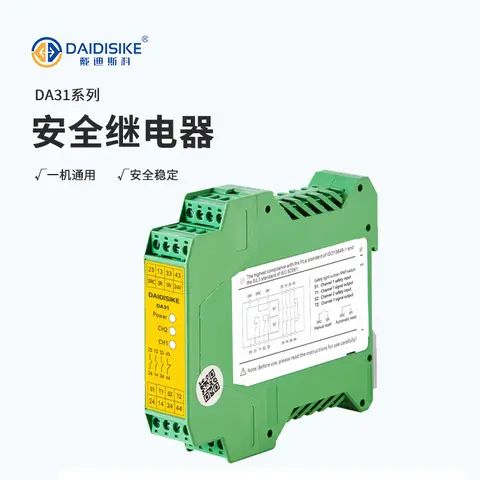
DA31 Emergency-Stop Safety Relay Module
Ultra-slim 22.6 mm Category 4/PL e/SIL 3 safety relay with dual-channel PNP/NPN input and a solid-state status output.
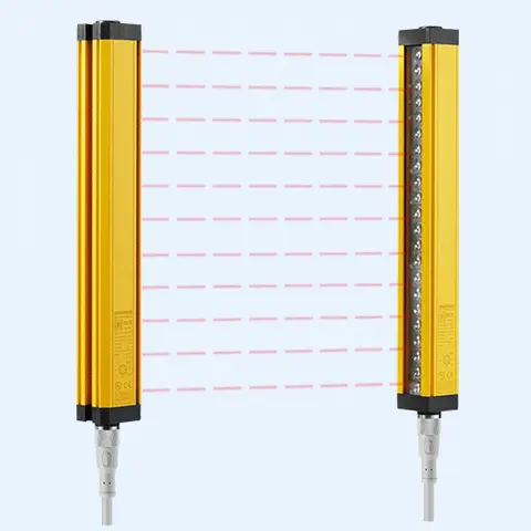
DCE Automation Safety Light Curtain
Compact through-beam safety light curtain in a 30 x 30 mm housing: 10/20/30/40 mm beam pitch, up to 72 beams, 0.3-3 m or 0.3-6 m sensing distance, NPN/PNP output. Catalogue-stated Type 4 design basis; confirm exact safety-document scope.
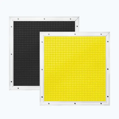
JT14 Safety Mat (Economical)
Economical pressure-sensitive safety mat with volt-free N.O. output for large-area or custom-shape floor guarding.
Related Products in Safety Door Locks & Switches
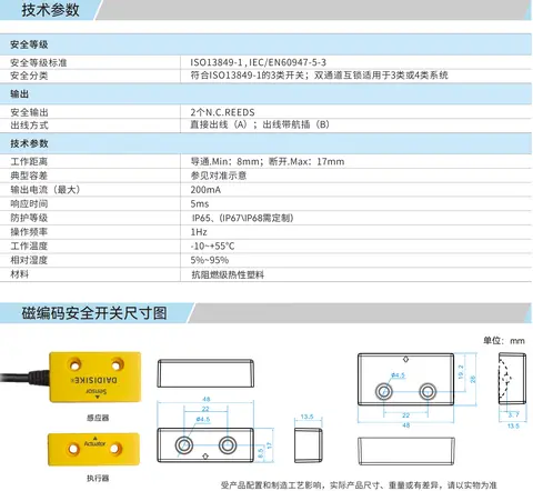
DX-C1 Magnetic Coded Safety Switch
Non-contact coded-magnet safety switch with 17 mm sensing range and high misalignment tolerance for guard doors.
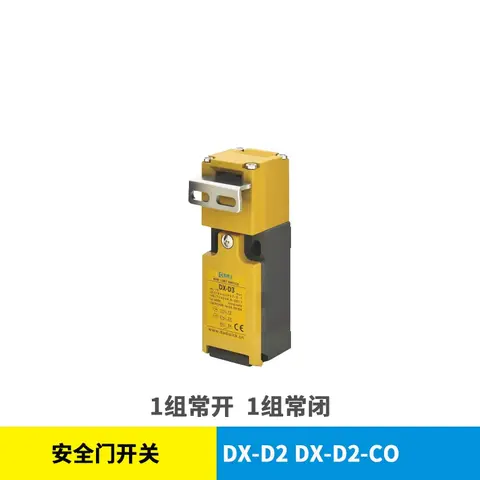
DX-D2 & DX-D3 Safety Door Switch
Mechanical NC/NO safety interlock switch, IP67, 1,000,000-cycle mechanical life, no locking function.
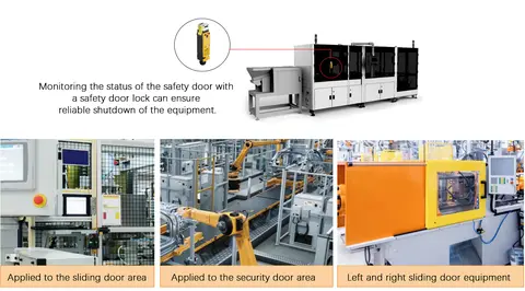
DX-K Series Safety Door Lock Operation Keys
11-model range of fixed and adjustable operation keys for DX-W2/W3/W5 and DX-D2/D3 safety door interlock switches.
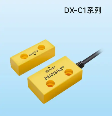
DX-R1 Non-contact Safety Switch (RFID Coded)
Non-contact RFID-coded safety switch, dual-channel PLe/Type 4 output, 0-10mm switch-on, cascadable, 8 NPN/PNP models.