
DX-W2 Safety Door Lock (Solenoid Guard Locking Interlock Switch)
Contact-type guard locking switch with 4 contact blocks in 14 NC/NO configurations and 1300 N holding force.
▶ Watch it in action: Safety Light Curtain + Guard-Locking Door Switch Interlock — Wiring Demo
 🔍 Click to enlarge · 1/21
Technical Specifications
| Output type | Mechanical contact type (C = NC, O = NO), 4 contact blocks, 14 combinations |
|---|---|
| Locking type | GD = electromagnetic locking / mechanical release; GC = mechanical locking / electromagnetic release |
| Head material | J = metal head / S = plastic head |
| Cable/conduit interface | G = M20 conduit entry (unwired as standard) / X = factory-fitted cable, 1.5 m |
| Solenoid voltage | 24 V DC ±10%, 4.8 W |
| Holding force | 1300 N |
| Protection rating | IP67 |
| Mechanical life | 1,000,000 operations |
| Electrical life | 150,000 operations |
| Contact ratings | AC-15 240V/3A; DC-13 30V/2.3A |
| Forced separation | ≥80 N / ≥10 mm |
| Operating temperature | -20°C to +60°C |
| Optional accessory | Rear manual unlock (DX-W2-L kit: sleeve + limit plate + 3× M4 screws + metal knob, 90° clockwise release) |
| Compatible actuator keys | DX-K series (11 keys) |
Overview
The DX-W2 is a mechanical-contact safety door lock (guard locking switch) that mechanically holds a machine guard door closed until a hazardous motion (e.g. a spindle running down) has come to a safe stop, then releases the lock via a solenoid. It reports two independent states through its contact blocks — the actuator key/tongue position and the lock status — so a safety relay or safety PLC can verify both "door closed" and "lock engaged" before allowing a machine to start.
It is intended for machine builders and panel integrators working with traditional relay-based (electromechanical) safety circuits, typically on CNC machine tools, injection/die-casting machines, and automated production-line fence access doors, where a coded/electronic (RFID) interlock is not required and a contact-output device that wires directly into existing relay logic is preferred.
Features & Benefits
Four contact blocks, 14 NC/NO configurations
Two independent contact compartments (head/actuator side and body/lock side) give four contact blocks in total, combinable into 14 patterns (CO/CO, 2C/2C, 3C/C, C/C2O, O/3C, 2C/2O, etc.) across 28 catalog models. This lets a panel builder pick exactly how many NC safety contacts and NO status/indication contacts are needed, without adding an external expansion relay.
1300 N holding force
The solenoid/mechanical lock mechanism holds 1300 N of force, resisting manual attempts to pull the guard door open while a machine's hazardous motion (e.g. spindle coast-down) is still in progress.
GD and GC locking-type versions
Every one of the 14 contact configurations is available in two locking types: GD (electromagnetic locking / mechanical release) and GC (mechanical locking / electromagnetic release), letting the safety-circuit designer choose the fail-safe behaviour that matches the application's risk assessment.
IP67-rated housing with gold-plated silver-alloy contacts
The switch is rated IP67 and built with a PA66 flame-retardant housing and gold-plated silver-alloy contact blocks, suited to environments with coolant spray, cutting oil mist, or dust around the guard door.
1,000,000 mechanical / 150,000 electrical operating cycles
Rated for 1,000,000 mechanical operating cycles and 150,000 electrical (contact-switching) cycles, giving a service-life margin for doors that are opened and closed frequently during shift changes, tooling, or maintenance.
Forced-separation escape function
In addition to normal solenoid-driven locking/unlocking, the mechanism supports forced separation (manual override) with ≥80 N force over ≥10 mm of travel, providing a way to open the door manually if power or the solenoid is unavailable.
24 V DC ±10% solenoid supply, 4.8 W
The solenoid operates on 24 V DC ±10% at 4.8 W (approximately 200 mA), matching the 24 V DC supply already present in most industrial control cabinets, so no separate high-voltage supply is needed for the locking mechanism itself.
Optional rear manual unlocking kit
An optional DX-W2-L accessory kit (sleeve sized to panel thickness, limit plate, 3× M4 screws, and a metal knob that releases with a 90° clockwise turn) adds a manual unlock point on the back of the guard, useful when the door needs to be opened from the machine-interior side.
Applications
Models & Ordering Information
GD Series — Electromagnetic Locking / Mechanical Release, Metal Head (M20 conduit entry)
GC Series — Mechanical Locking / Electromagnetic Release, Metal Head (M20 conduit entry)
PDF & 3D CAD Downloads
Browse all downloadsDX-W2 Safety Door Lock Technical Data Sheet
Find the file for your exact model
Open the download center with this series selected. Search the full model, check the file details, and download the matching CAD file.
Confirm the document and CAD file match the exact ordered version before installation or mechanical design. Contact us if your model is not listed.
How to Select
- Choose the head-side/body-side contact pattern (C = 1×NC, O = 1×NO, CO = 1×NC+1×NO, 2C = 2×NC, 3C = 3×NC, C2O = 1×NC+2×NO, 2CO = 2×NC+1×NO, 2O = 2×NO) based on how many NC (safety) and NO (status) contacts your circuit needs; 14 combinations are offered.
- Select GC (mechanical locking, electromagnetic release) or GD (electromagnetic locking, mechanical release) based on the fail-safe behaviour your risk assessment requires when power is lost.
- Choose G (M20 conduit entry, unwired, for field wiring) or X (factory-fitted 1.5 m cable, customizable length) for the cable/conduit interface.
- Choose J (metal head) for higher-mechanical-stress or metalworking environments, or S (plastic head) as a lighter-duty, lower-cost option.
- Match the switch to one of the 11 DX-K series operating keys based on door hinge geometry and approach angle; for hinged doors a door radius R > 300 mm is required, with a key positioning tolerance of ±1 mm.
- Add the optional DX-W2-L accessory kit if back-side (machine-interior) manual release is required.
📘 Need the full method? How to Choose a Safety Door Switch / Interlock
When NOT to specify the DX-W2 — and what to use instead
The application needs RFID-coded or electronic transistor output rather than mechanical contacts.
Why not: DX-W2 is a mechanical-contact device (C/O contact blocks) intended for relay-based circuits; it has no RFID coding or transistor output.
Use instead: DX-D6 guard-locking switch for RFID + NPN/PNP output, or DX-R1 for non-contact monitoring only
The risk assessment calculates guard-opening forces above the rated 1300 N holding force.
Why not: 1300 N is DX-W2's published holding force; loads above this exceed the documented capability of the lock.
Use instead: DX-D6 (2000 N holding force) if an electronic RFID output is acceptable, or consult the factory for supplementary restraint
The door is opened and closed at a rate that will exceed 150,000 electrical (contact-switching) operations over the machine's service life.
Why not: DX-W2's rated electrical life is 150,000 operations (versus 1,000,000 mechanical operations).
Use instead: DX-W5, whose electrical life is rated at greater than 150,000 operations
Only one or two safety-contact channels are needed and the extra contact blocks would go unused.
Why not: DX-W2 provides four contact blocks across 14 combinations, more than a single- or dual-channel circuit typically requires.
Use instead: DX-W3, the simplified 2-contact-block version of the same platform
The project needs a published PFHd, or an independently issued certificate number rather than a design-basis claim.
Why not: DX-W2 is a mechanical-contact interlock with no PFHd/B10d/MTTFd or certificate number published; certification documents are supplied only on request.
Use instead: Request the certification package from the factory and validate the complete circuit with a DA31 or DQSRN safety relay
Specifications we do not publish yet
We only publish a figure once we are confident it is true. The items below are still being validated through further testing and real-world customer feedback, so for now we would rather leave them open than guess. If one of them matters to your design, ask us for the latest validated status.
- PFHd / B10d / MTTFd reliability figures
- Certificate number and scope for the design basis
- Overall body dimensions and weight
- Connector pin-out for the X (factory-fitted cable) variant
- Approach speed / minimum safety-distance guidance per ISO 13855
- Coating/finish corrosion-resistance rating beyond the PA66 housing note
Frequently Asked Questions
What does "GD" and "GC" mean in the DX-W2 order code?
How many contacts does the DX-W2 have, and can I choose the NC/NO mix?
What is the holding force of the DX-W2 lock?
What voltage does the solenoid operate on?
What is the protection (ingress) rating of the DX-W2?
What is the mechanical and electrical life of the DX-W2?
Can the DX-W2 be opened manually if there is a power failure or the solenoid does not release?
What contact ratings does the DX-W2 support?
What is the operating temperature range?
Does the DX-W2 use a contact (relay-wired) output or an electronic/coded (RFID) output?
What operating key options are available for the DX-W2?
Can you provide certification documents for the DX-W2, such as CE?
Related Categories and Example Products
Explore other functions that may be needed in a machine or line. The products below are category examples, not pre-validated electrical or safety combinations. Confirm each interface and application separately: Safety Relays · Safety Light Curtains · Safety Mats
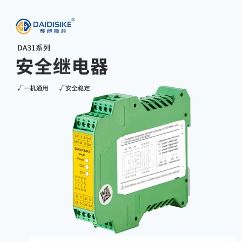
DA31 Emergency-Stop Safety Relay Module
Ultra-slim 22.6 mm Category 4/PL e/SIL 3 safety relay with dual-channel PNP/NPN input and a solid-state status output.
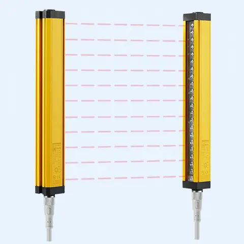
DCE Automation Safety Light Curtain
Compact through-beam safety light curtain in a 30 x 30 mm housing: 10/20/30/40 mm beam pitch, up to 72 beams, 0.3-3 m or 0.3-6 m sensing distance, NPN/PNP output. Catalogue-stated Type 4 design basis; confirm exact safety-document scope.
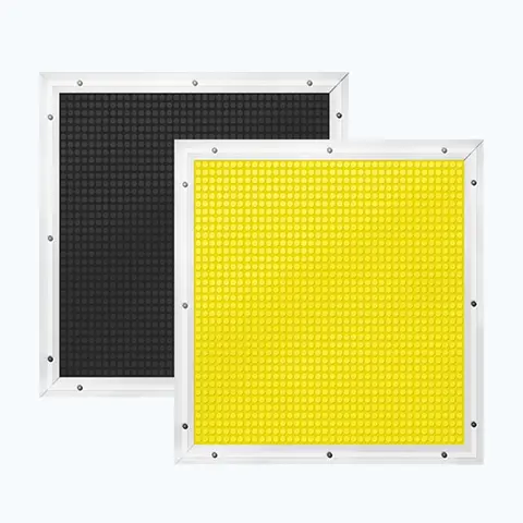
JT14 Safety Mat (Economical)
Economical pressure-sensitive safety mat with volt-free N.O. output for large-area or custom-shape floor guarding.
Related Products in Safety Door Locks & Switches
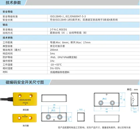
DX-C1 Magnetic Coded Safety Switch
Non-contact coded-magnet safety switch with 17 mm sensing range and high misalignment tolerance for guard doors.
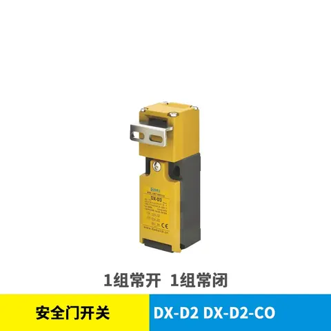
DX-D2 & DX-D3 Safety Door Switch
Mechanical NC/NO safety interlock switch, IP67, 1,000,000-cycle mechanical life, no locking function.
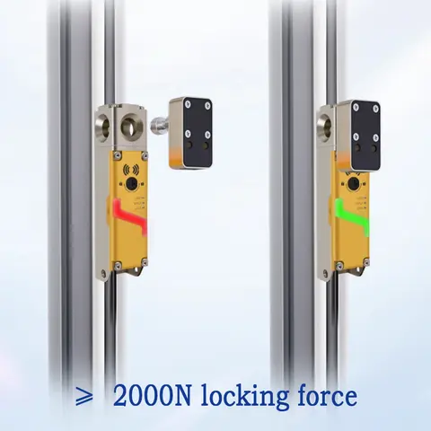
DX-D6 Guard Locking Safety-Door Switch
Guard locking safety-door switch: 2000 N holding force, redundant dual outputs, RFID-coded actuators.
DX-K Series Safety Door Lock Operation Keys
11-model range of fixed and adjustable operation keys for DX-W2/W3/W5 and DX-D2/D3 safety door interlock switches.