
How to Choose a Safety Door Switch / Interlock
A safety door switch (interlock) reports the state of a movable guard — a door, gate, or hatch — to the machine's safety circuit. A compatible safety-control system and final switching elements perform the required stop; the switch alone does not stop hazardous motion. A guard-locking version also physically holds the guard until release is permitted by the validated safety function. Select the complete arrangement from the machine risk assessment.
The selection logic runs in a fixed order: first decide whether you need plain interlocking or guard locking; then the locking principle and holding force; then contact-type versus non-contact sensing; then the coding level against defeat; and finally contacts, wiring, and mechanical accessories.
This guide follows that order, using DAIDISIKE's DX family as concrete examples: the DX-D2/D3 mechanical door switches, the DX-W2/W3/W5 and DX-D6 guard-locking switches, the DX-C1 coded-magnet and DX-R1 non-contact switches, the DXL door bolt, and the DX-K key/actuator system.
Door Switch or Door Lock: Do You Need Guard Locking?
Compare the total time to reach a safe state with the time in which a person can access the hazard after the guard opens. A non-locking interlock may be appropriate only where the complete risk assessment and positioning requirements permit it. DX-D2/DX-D3 is a mechanical contact-interlock example with no guard-locking function; its contact data does not prove that every possible welded-contact fault is detected.
If access could occur before the hazard ends, determine the required guard-locking function and safe release conditions. Process locking and personnel-protection locking are not interchangeable. DX-W2/W3/W5 and DX-D6 offer locking arrangements, but each exact mechanism, output and application needs verification.
A third option covers full-body-access doors: the DXL safety door bolt is a purely mechanical slide bolt (48 mm bolt travel, door gaps 1–10 mm, rated 1,000,000 operations) whose base directly accepts DX-W2, DX-W3, DX-D2, or DX-D3 switches — combining a robust handle mechanism with the electrical interlock in one assembly.
Decision to record: monitoring only, process locking, or personnel-protection locking, together with the machine's safe-release requirement. Compare mechanical DX-D2/DX-D3 monitoring with DX-D6 electronic guard locking; the door-switch category comparison also includes the other locking and non-contact families.
Step 1: Power-to-Release or Power-to-Lock?
Guard-locking switches come in two locking principles, and the choice follows from your risk assessment, not preference.
Power-to-release (mechanically locked, solenoid released — DAIDISIKE code GC, or the DX-D6 C-type): a spring holds the lock; energizing the solenoid releases it. On power failure the door stays locked. This is the usual choice when the hazard is the machine itself, because a power cut must not let anyone walk into a coasting mechanism. Plan an escape/maintenance release strategy for people who could be locked inside a cell.
Power-to-lock (solenoid locked, mechanically released — code GD, or the DX-D6 D-type): the solenoid holds the lock only while energized; loss of power releases its electromagnetic holding action. Select this only where the risk assessment permits that behaviour. The DX-W2, DX-W3 and DX-W5 catalogue includes GD/GC, and DX-D6 includes C/D; confirm the exact model's release arrangement, circuit and installation rather than assuming the electrical or mechanical design carries over.
Decision to record: the required state after power loss, the condition for unlocking, and any escape/maintenance-release provisions. The DX-D6 C/D comparison and DX-W2 contact-lock options provide different documented configurations to evaluate.
Step 2: How Much Holding Force Does the Door Need?
Holding force is what stops a person from simply pulling the locked door open. Size it against the realistic pull a person can apply to your door geometry — a large door with a long lever arm needs more margin than a small hatch.
DX-W2/W3/W5 publish a 1300 N holding-force figure and DX-D6 2000 N. Verify what the manufacturer's figure represents, the exact actuator and mounting conditions, and the forces arising from the door geometry. Those numbers alone do not establish suitability for every walk-in cell door.
Also check the solenoid supply: the DX-W2 solenoid runs on 24 V DC ±10% at roughly 200 mA (4.8 W); the DX-W5 additionally offers a 10–115 V AC/DC solenoid option for mixed-voltage retrofits. Mechanical life matters on high-traffic doors — the DX-W2 is rated 1,000,000 mechanical operations (150,000 electrical).
Decision to record: required holding force, door motion/lever arm, guard stops and mounting constraints. Use the DX-D6 technical sheet for its published holding-force and installation data; use the selected model's own document rather than transferring those values to another family.
Step 3: Contact-Type or Non-Contact Sensing?
Contact-type (key-actuated) switches like the DX-D2/D3 and the DX-W lock family use a metal key on the door entering the switch head. Strengths: positive mechanical engagement, forced contact separation, and — on locking types — the holding function itself. Weaknesses: they demand door alignment within about a millimeter, wear with traffic, and collect debris in the key slot.
Non-contact switches remove the mechanical key coupling. DX-C1 publishes a sensing distance up to 17 mm; this is not a guaranteed 17 mm door-offset tolerance. Obtain the exact actuator's assured switching distances and permitted alignment envelope. Its catalogue lists IP65 as standard with IP67/IP68 options, whose actual washdown conditions still require checking. The DX-R1 non-contact switch gives an assured switch-on distance of 0–10 mm and assured switch-off above 25 mm, with dual-channel solid-state outputs (150 mA) plus a 50 mA auxiliary output, a 60 ms response time, and IP65 protection.
Non-contact sensing may tolerate a different alignment envelope and avoid mechanical key wear, but washdown suitability and assured switching distances remain model-specific. DX-D6 combines non-contact coded sensing with guard locking, so 'non-contact' must not be treated as meaning 'cannot lock'.
For monitoring without physical locking, compare DX-C1 coded magnetic sensing and DX-R1 non-contact sensing against the target alignment, environment and safety input. If locking is needed as well, return to DX-D6's exact model selection.
Step 4: What Coding Level Do You Need Against Defeat (ISO 14119)?
Defeat prevention is part of interlock selection and application. ISO 14119:2024 addresses interlocking-device design, selection and foreseeable defeat; coding is one measure, not a complete prevention strategy.
Catalogue labels such as universal-coded S and unique-coded D describe actuator pairing. They must not automatically be translated into an ISO 14119 high coding level. Obtain the exact model's declared coding level, teach/replacement procedure and actuator compatibility; apply the prescribed installation and defeat-prevention measures.
Assess why an operator might bypass the guard and provide a safe way to perform the task. DX-D6 uses its own coded key system, DX-K9S/DX-K9D, separate from the mechanical DX-K1–K8 keys. Specify the required coding and installation measures from the assessment and exact evidence, not the letters S/D alone.
The ISO 14119:2024 scope covers selection and defeat minimisation. The DX-D6 configuration page distinguishes the lock mechanism, outputs, connector and actuator; these are separate ordering decisions.
Step 5: Contacts, Outputs, and Wiring Into the Safety Circuit
For contact-type switches, pick the NC/NO complement to match your safety relay and any auxiliary signaling. The DX-D2/D3 range offers four configurations (1NC+1NO, 2NC, 2NC+1NO, 3NC); the DX-W2 offers 14 contact configurations across two independent contact compartments — 28 catalog models across the two locking types — letting one compartment monitor the door and the other monitor the lock. The DX-W5 provides six gold-plated silver-alloy contact blocks in four configurations, with contact ratings including AC-15 240 V/3 A and a DC-13 250 V/2.7 A tier.
DX-R1 lists four-wire and six-wire versions with different connection arrangements. Do not assume DX-R1, DX-C1 and DX-D6 can all be placed in one interchangeable series chain. Obtain the approved circuit, maximum device count, diagnostic/fault-masking assessment, response-time calculation and compatible safety input for the exact combination.
Use a suitable safety relay or controller selected for the exact input and required functions. DQSRN supports manual and automatic reset according to the selected model's instructions; EDM capability remains unconfirmed. DA31 must be checked against its own documentation. DX-D6's published function table adds EDM and Reset on H compared with standard R, but the exact wiring and complete circuit still need verification. Where restart interlocking, safe release or final-element monitoring is required, establish how the complete circuit provides and validates those functions.
Use the safety-relay comparison for documented input/contact differences, not as a blanket cascade approval. The NPN/PNP compatibility guide supports the electrical selection but does not establish a safety architecture.
Step 6: Keys, Actuators, and Mechanical Installation
Actuator selection is where door-switch projects most often stumble on site. DAIDISIKE's DX-K operation key series (11 models, DX-K1 through DX-K8 with variants) fits the DX-W2, DX-W3, DX-W5, DX-D2, and DX-D3 switch bodies, with a specified key-to-slot insertion tolerance of ±1 mm.
Match the key to the door movement: sliding doors can use rigid straight keys, while hinged doors need either an angled-entry key or an adjustable one — the DX-K5 adjusts horizontally, the DX-K6 horizontally and vertically, and the DX-K8 adds a press-3 mm, rotate-90° operating head for awkward geometries. Hinged (swing) door installations require a minimum swing radius of R > 300 mm; tighter radii bind the key in the slot and wear the head.
Leave preparation clearance before fitting — 1–3.5 mm for the DX-W2/W3/W5 family, 1–2.5 mm for DX-D2/D3. The DXL bolt assembly is a mechanical option for compatible switches, with a 1–10 mm door-gap specification; it does not replace the full-body-access assessment, escape provisions or electrical safeguard.
DX-D6 uses a separate DX-K9 system. Match DX-K9S/DX-K9D to the ordered coding. Its accessory sheet lists DX-K9-L/DX-K9-L1 for left/right-opening hinged doors and DX-K9-T1/DX-K9-T2 for left/right-opening sliding doors; confirm the direction against the drawing and actual mounting view. Match the standard 8-pin or high-function 12-pin cable to the ordered R/H and A/B version.
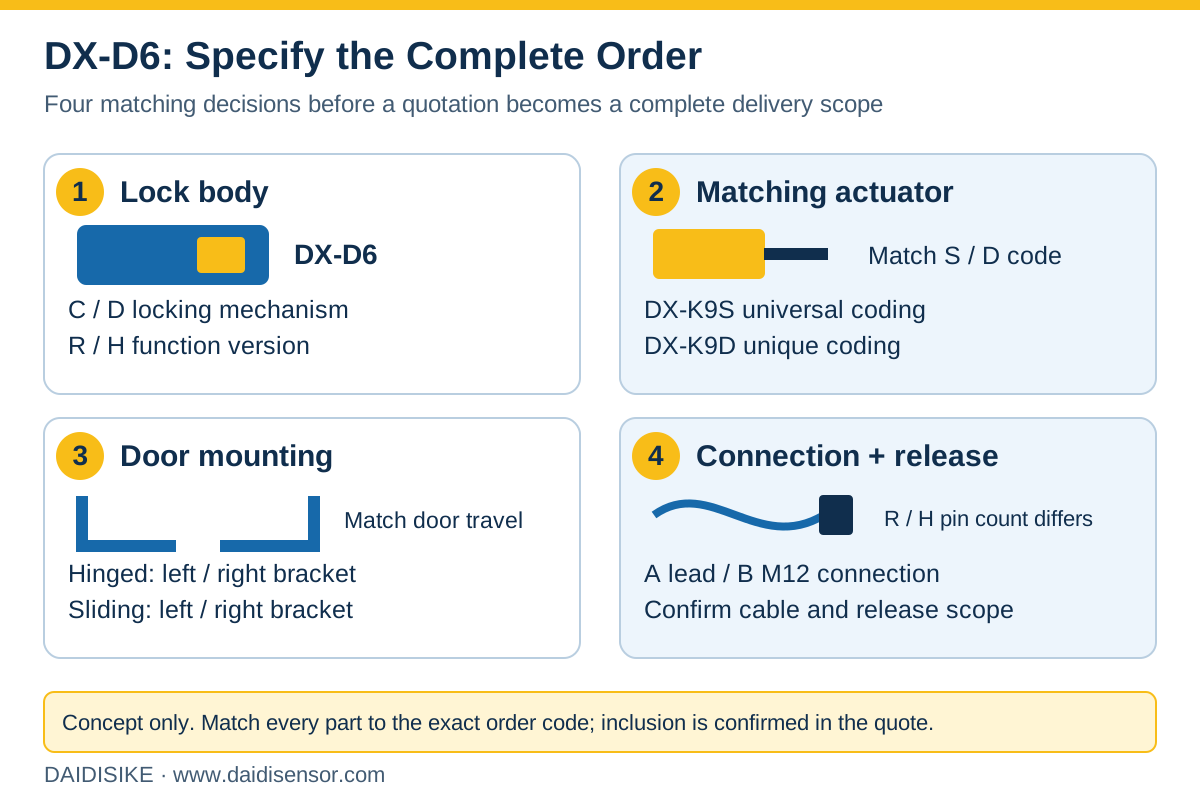
Use the DX-D6 matched-set checklist for its actuator, bracket and cable choices. For DX-W2/W3/W5 or DX-D2/D3, use the separate DX-K mechanical operation-key range. A DXL mechanical bolt is not itself an electrical safeguard.
For full-body entry and several kinds of access in one cell, the robot sensor-role application guide shows why a door device cannot also prove that the entire floor space is empty.
Finish with a Complete Configuration and Open-Item List
For an initial quotation, send the machine/task, door motion and opening direction, full-body-access needs, expected holding force, power-loss strategy, controller/input type, quantity and available layout or photographs. These inputs support a preliminary selection; they do not by themselves validate the final safety function.
Before placing the order, record the full switch code, actuator and coding, bracket/bolt, output/contact version, cable/connector and length, release provisions, document revision, included accessories and unresolved confirmation items. Obtain the exact wiring and required certification/reliability documents through the quotation; do not infer them from the family name.
Return to the safety-door switch and guard-lock comparison if the family is still undecided. For a defined DX-D6 configuration, use its model-aware quotation form and include the requested accessory set in the message. The machine builder or qualified integrator must validate installation, release, restart and the complete safety circuit.