
How to Choose a 2D LiDAR Scanner
A 2D LiDAR measures distances in a scanning plane and can provide a distance profile, ordinary switching signals or both. Coverage, range and interfaces vary by model. It may simplify an area-detection task, but it does not necessarily replace several point sensors or provide personnel protection.
Start by distinguishing a personnel-safety function from ordinary obstacle detection or measurement. Then decide whether the receiving system needs discrete outputs or point-cloud data. These are separate selection decisions; an Ethernet interface or a stop-labelled output does not confer a safety rating.
This guide takes you through the selection in six steps, using DAIDISIKE's DLD and SDLD series as worked examples: the DLD05A3 and DLD20A5 discrete-output obstacle-avoidance scanners, the DLD30T, DLD-50D, and DLD-100D Ethernet measuring scanners, the DLD50T8 that offers both interfaces, and the SDLD-05A AGV scanner.
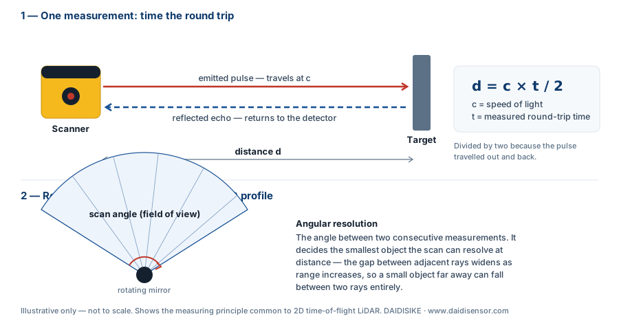
What Is a 2D LiDAR Scanner and When Do You Need One?
A 2D scanner samples one plane rather than the complete surrounding volume. Check the sensing technology, wavelength and laser classification on the actual model label and manual; these are not identical across every product sold as LiDAR.
Consider a 2D scanner when the task needs wide-angle area coverage, multiple distance-dependent ordinary control actions, changing zones or distance-profile data. Example warning/slowdown distances are application settings, not personnel-safety limits. For a single-point task, a photoelectric or laser-distance sensor may be simpler.
One caution up front: a general-purpose 2D LiDAR is not automatically a certified safety laser scanner. If your risk assessment calls for a safety-rated device, that requirement drives the selection before any performance spec — see the final section.
The LiDAR series comparison separates safety scanners, switching detectors and measuring models. Select the function first, then compare the exact output version and the target conditions.
Step 1: Discrete Switching Outputs or Point-Cloud Data?
Decide first how the scanner will talk to your system, because it splits the market in two.
Discrete-output scanners behave electrically like a photoelectric sensor. The DAIDISIKE DLD05A3 and DLD20A5 output three switching signals (NPN or PNP, rated DC30V/50 mA max) plus one status signal — no fieldbus, no protocol stack, no SDK. You configure detection zones once over USB; afterwards the scanner runs standalone and drives PLC inputs directly. This is the right choice for AGV retrofits and machine builders without a software team.
Point-cloud scanners output measurement data over Ethernet for navigation, mapping, and profiling software. The DLD30T (30 m), DLD-50D (50 m), and DLD-100D (100 m) all stream data over 100BASE-TX Ethernet. Choose these when a computer or robot controller will consume the data.
The DLD50T8N/P combines Ethernet data and a discrete NPN/PNP output; that output is for ordinary interlock or pre-warning use, not a certified safety OSSD. It is different equipment from the Ethernet measuring DLD-50D, not another order-code group for the same device. SDLD-05A combines Ethernet and digital I/O for ordinary AGV detection. Confirm the specific interface, output count and software version from the selected model rather than treating these arrangements as identical.
Why the Same Scanner Has Two Very Different Range Figures
Nothing in a LiDAR datasheet causes more mis-specification than range, because the same unit is legitimately quoted with two numbers that differ by a factor of four or more — and they are not measuring the same thing.
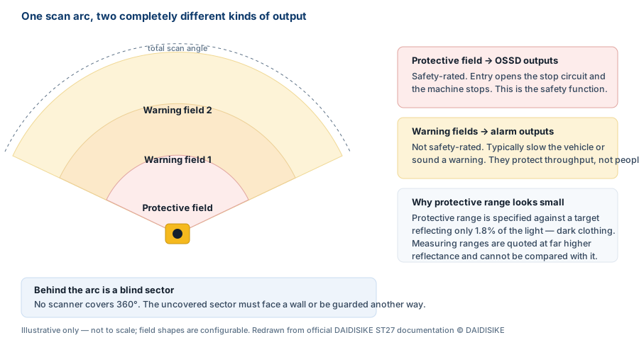
Returned optical energy depends on the target, angle, surface and environment. A 90% or 10% remission specification describes a defined test target; it is not a reliable conversion table for every white board, cardboard box or garment. Compare the targets and conditions attached to each range figure.
A safety protective-field limit, warning-field limit and ordinary measuring range are different specifications. The exact safety scanner's manual defines the relevant test object and remission conditions. An ordinary 20 m or 30 m range does not imply any certified protective field at all.
The same physics quietly reduces performance in service. A target that was white when the line was commissioned and is now grey with dust returns less light, and the usable range falls with it — one of the reasons a scanner that worked at handover can start missing objects months later without anything having been changed.
Step 2: How Much Range Do You Really Need?
Read both the high- and low-remission limits where published, then validate the actual target. DLD-50D lists 50 m at 90% and 20 m at 10%; DLD30T lists 30 m at 90% and 10 m at 10%; DLD-100D lists 100 m at 90% and 40 m at 10%. These model data are measurement limits under stated conditions, not guarantees for every dark obstacle or person.
For ordinary obstacle avoidance, work backwards from the vehicle's measured behaviour and required coverage. DLD05A3 and DLD20A5 offer different ranges in a similar housing, while SDLD-05A publishes range figures at different target reflectivities. A physical drop-in fit does not establish software compatibility, sufficient response time or a personnel-safety function.
Do not ignore minimum range. A scanner blind below 0.3 m can miss an obstacle a docking robot is about to touch; the DLD05A3 and DLD20A5 start detecting at 0.05 m, keeping the near-field blind zone small.
Step 3: What Field of View and Blind Sector Can You Live With?
Field of view determines mounting position. A 270° scanner mounted on a vehicle corner covers two full sides at once; that is the geometry of the DLD05A3, DLD20A5, DLD30T, and SDLD-05A. The DLD-50D and DLD50T8 scan 280°, and the DLD-100D family includes a 360° variant (DLD-100DC) for mast or overhead mounting where all-round coverage matters.
Every non-360° scanner has a blind sector behind it — the DLD-50D, for instance, has an 80° blind sector spanning 320°–0°–40°. Point the blind sector at the vehicle body or the wall, and check that brackets, cables, and chassis edges do not intrude into the active arc.
Also verify the scan plane itself: a 2D scanner sees only one horizontal slice. Obstacles below the plane (forks, pallets on the floor) or above it (overhanging racks) are invisible, so mounting height is part of the safety concept, not an afterthought.
Step 4: What Angular Resolution and Scan Frequency Do You Need?
Angular step determines geometric spacing between neighbouring samples. At 0.1 degrees and 5 m, the arc spacing is about 8.7 mm; at 0.3 degrees it is about 26.2 mm. That arithmetic is not a guaranteed minimum detectable object: beam size, target return, processing and settings also matter. Separately listed frequency and angular-step options do not establish which combinations are supported.
Scan frequency sets how often the picture refreshes: 15/30 Hz on the DLD05A3 and DLD20A5, 10–30 Hz adjustable on the DLD30T, and variant-dependent settings on the DLD-50D and DLD-100D. DLD-100DP specifies fixed 100 Hz and 0.32°. DLD-100DH/DC list 50/25 Hz and 0.08°/0.16°/0.32° as separate option sets; confirm their supported pairings for the ordered variant instead of constructing a combination matrix from those lists.
Higher frequency may change the available angular step. Weigh sample spacing against the complete acquisition and controller response, then request the supported settings for the exact model and firmware before committing.
Geometric spacing is not guaranteed detection capability. Beam footprint, target return, filtering and the actual scanner's specified conditions also matter. These settings are examples, not a model-specific safety-field configuration.
Freeze the Exact Model Before Ordering a Sample
- State the complete model and output version on the quote, not only a 50 m or 100 m range label. DLD-50D and DLD50T8 require separate equipment selections.
- Match the manual, wiring, firmware and configuration tool to that selection. A shared DLD-50D reference does not verify DLD50T8 specifications or DLD-50G hardware.
- For DLD-50G, obtain dedicated range, accuracy, scan-angle, frequency and interface evidence before design; these parameters are not established by the shared reference.
Use the existing LiDAR procurement comparison to shortlist the DLD-50D measuring variants, DLD50T8 N/P devices or DLD-100D variants. If the request names DLD-50G, keep the unverified fields open for model confirmation.
Step 5: How Will You Configure Zones and Switch Between Them?
For obstacle avoidance, zone architecture matters more than raw specs. The DLD05A3 and DLD20A5 store 16 zone sets, each defining 3 nested detection zones mapped to the 3 switching outputs — the classic warning / slow-down / stop sequence, hard-wired. Zone sets are configured once over Micro-USB and switched in operation as vehicle conditions change: straight travel, turning, docking.
SDLD-05A provides configurable zone groups and controller inputs. Check the exact software/manual revision for supported shapes, vertex counts, input selection and filtering. A hold-time or object-size filter can add latency or exclude targets; include the complete configured response in the ordinary obstacle-avoidance design rather than quoting a hardware response alone.
Sketch your zone geometry per driving state before choosing hardware, then confirm the zone shapes, vertex counts, and switching inputs the scanner supports. Running out of zone sets mid-project is a painful discovery.
Step 6: Power, Environment, and Mounting Constraints
On mobile platforms, size and power budget are hard limits. The DLD05A3 measures 50 × 50 × 76 mm at 150 g on DC9–28V; the DLD-50D draws just 2.5 W from DC9–36V; the SDLD-05A weighs 374 g including cable and draws ≤2.5 W. All fit small battery-powered chassis.
Match the IP rating to the environment: IP65 on the DLD05A3/DLD20A5 handles dust and light moisture; IP67 on the DLD30T, DLD-50D, DLD50T8, and DLD-100D suits harsher or outdoor-adjacent duty; the SDLD-05A is IP54, for indoor vehicles. Check ambient light immunity for sunlit sites — the DLD-50D withstands over 100,000 lux and the DLD-100D over 80,000 lux, and the DLD-100D adds multi-echo processing to help in dust, rain, and fog.
Confirm the exact temperature range and laser class, including installation and service restrictions. A Class 1 label concerns accessible laser radiation during normal use; it is not a blanket exemption from the manual, damage checks or qualified maintenance, and it does not certify the machine-safety function.
The UK Health Security Agency's laser-class guidance distinguishes normal-use classifications. Apply it together with the scanner's own instructions, not as proof of a DAIDISIKE model's classification.
What Degrades a LiDAR Reading in Service
A scanner measures light that comes back, so anything between the unit and the target competes with the echo it is trying to time.
Airborne particulate is the main one. Fog, steam, welding smoke and heavy dust scatter the outgoing pulse and return a partial echo from the air itself, which the scanner can read as a phantom object close in, or which can mask a real object further out. Rain and snow do the same intermittently, which is why an outdoor installation needs a scanner rated for it and a field configuration with tolerance for isolated returns.
Direct sunlight into the receiver raises the noise floor and shortens usable range, so scanners are usually specified with an ambient light immunity figure. Mounting the unit so that the sun cannot sit in its field at any point in the day is cheaper than compensating for it later.
Mutual interference matters as soon as there is more than one scanner. Two units whose fields overlap can read each other’s pulses unless the series implements interference rejection. Confirm that capability before designing a cell with several scanners rather than discovering it during commissioning.
Finally the window itself. A contaminated or scratched front window attenuates both the outgoing pulse and the echo. Units intended for safety duty monitor window contamination and report it as a fault — a feature worth having, because the alternative is a scanner that degrades silently.
Mounting Geometry Decides Whether the Scan Plane Is Useful
A 2D scanner sees one plane. Everything above and below that plane is invisible to it, and this single fact causes more field problems than any electrical parameter.
Mounted horizontally at ankle height on an AGV, the scan plane detects a person standing in the path but not a shelf overhanging at chest height, and not a fork protruding at knee height from a stationary pallet truck. Mounted higher it sees the obstruction and misses the feet. Neither is wrong; both need to be a deliberate decision recorded in the risk assessment rather than a consequence of where the bracket fitted.
On mobile platforms the plane also moves with the vehicle. Ramps, thresholds and floor joints tilt the plane into the ground or up into free space, producing either spurious stops or a gap in coverage exactly where the vehicle is least stable. Check the extremes of the route, not the flat section.
Two more geometric checks are worth running before drilling anything. Reflective floors and glossy machine panels inside the scan plane can produce mirror returns that appear as objects where none exist. And the blind sector behind the scan arc must face a wall, a structure or another guarded approach — an unguarded blind sector is simply an unguarded approach.
Is a 2D LiDAR a Certified Safety Laser Scanner?
No. A personnel-safety scanner must have appropriate device evidence and be integrated into a validated safety function. Ordinary obstacle or navigation outputs do not become safety outputs because software labels a zone 'protective' or 'stop'.
DLD and SDLD models discussed here are ordinary detection or measurement equipment. The current catalogue's safety-scanner example is ST27, with its separately documented Type 3/PL d/SIL 2 design and protective-field variants. Request exact-model and version evidence; a catalogue statement alone does not validate an installation.
Separate the mandatory risk-reduction function from throughput aids. A validated safeguard may protect access, while an ordinary LiDAR adds early warning or navigation data. Do not count the same unverified ordinary output as a second safety layer.
Compare the ST27 protective-field variants only when the application requires a safety scanner. For a mixed robot installation, the robot sensor-role guide separates floor protection, fixed openings and process measurement.
Before requesting a quote, provide target size/reflectivity, required coverage, blind-sector layout, mounting height, controller interface, configured latency, environment and—where relevant—the required safety performance. The NPN/PNP output guide addresses ordinary input compatibility.