
ST27 Series Safety Laser Scanner (Type 3 ESPE, 3 m / 5 m Protective · 20 m Warning · 60 m Measuring)
A Type 3 safety laser scanner for machine builders and AGV/AMR integrators who must stop a machine when a person enters a hazardous area — it replaces fences and multiple light curtains with one 276° horizontal protective field of 3 m or 5 m, wired straight to a safety relay or safety PLC by OSSD.
 🔍 Click to enlarge · 1/8
Technical Specifications
| Product Category | Type 3 electro-sensitive protective equipment (ESPE / AOPDDR) |
|---|---|
| Type | Type 3 (IEC 61496) |
| Safety Integrity Level | SIL 2 (IEC 61508) |
| Category | Cat. 3 (ISO 13849) |
| Performance Level | PL d (ISO 13849) |
| Protective Field Range (@1.8% remission) | 3 m (ST27-03x) / 5 m (ST27-05x) |
| Warning Field Range (@10% remission) | 10 m (ST27-03x) / 20 m (ST27-05x) |
| Measuring Range (@70% remission) | 40 m (ST27-03x) / 60 m (ST27-05x) |
| Safety Output (OSSD) | PNP output — ON: max. IOUT = 100 mA, VOUT ≥ VCC − 2 V; OFF: IOUT < 1 mA, VOUT < 2 V; overcurrent protection |
| Auxiliary Output | PNP output — max. IOUT = 100 mA, VOUT ≥ VCC − 2 V; OFF: IOUT < 1 mA, VOUT < 2 V; overcurrent protection |
| Interface Options | PNP OSSD (S) / PNP OSSD + Ethernet (D) / Profinet (P) |
| Laser Source | 905 nm, Class 1 laser product (IEC 60825-1:2014) |
| Scanning Angle | 276° |
| Angular Resolution | 0.1° |
| Scanning Frequency | 30 Hz |
| Response Time | 100 ms (configurable) |
| Object Resolution | 70 mm at maximum protective-field radius |
| Extension Distance ZR | 350 mm |
| Tolerance Zone | 65 mm |
| Distance Deviation | ±2 cm |
| Repeatability | ±4 mm @ 1 sigma |
| Static Input Configuration | 6 sets (12 pcs) |
| Dynamic Input Configuration | 4 sets (8 pcs) |
| Contour Detection | 4 pcs |
| Max. Static Field Sets | 64 |
| Max. Monitoring Field Sets | 256 |
| Supply Voltage | DC 24 V ±20% |
| Power Consumption | < 4 W (no load) |
| Power-up Time | 10 s (typical) |
| Dimensions | 80 mm × 80 mm × 79.5 mm |
| Weight | 405 g |
| Housing Colour | Yellow |
| Enclosure Rating | IP65 |
| Ambient Temperature | Operating −10 °C to 50 °C (window free of frost and misting); Storage −40 °C to 70 °C |
| Ambient Humidity | Operating / Storage 35% RH to 95% RH |
| Ambient Light Immunity | 3000 Lux (incandescent) |
| Vibration Resistance | 10 Hz to 55 Hz, amplitude 0.35 ± 0.05 mm, 20 cycles per axis (X/Y/Z); 5M1 per IEC 60721-3-5 |
| Shock Resistance | 1000 ± 10 shocks per axis (X/Y/Z), 16 ms pulse; 5M1 per IEC 60721-3-5, 50 m/s², 11 ms |
| EMC | EN 61326-1:2013; EN 61000-4-2 / -4-3 / -4-4 / -4-6 / -4-8 |
| Design Standards | IEC 61496-1:2020, IEC 61496-3:2019, UL 61496-1:2021, IEC 61508:2020, IEC 62061, ISO 13855, IEC 61326-1, IEC 60825-1:2014 |
Overview
The ST27 series is a safety laser scanner (safety LiDAR) built for machine and vehicle safeguarding. It is an active opto-electronic protective device responsive to diffuse reflection (AOPDDR) — the category of electro-sensitive protective equipment (ESPE) defined by IEC 61496-3 — and it is rated Type 3 to IEC 61496-1, SIL 2 to IEC 61508 and Category 3 / Performance Level d to ISO 13849.
The scanner sweeps a 905 nm Class 1 laser beam through a 276° panoramic field at 30 Hz with 0.1° angular resolution, measuring distance by time of flight. Anything entering the configured protective field switches the safety output (OSSD) off within the configured response time; the separate warning field can be used first to slow a machine or sound an alarm before a stop becomes necessary.
Two ranges and three output types make up six models. The 03x models have a 3 m protective field, the 05x models a 5 m protective field. Output is either PNP OSSD (S), PNP OSSD plus Ethernet (D), or Profinet (P). All six share the same 80 × 80 × 79.5 mm IP65 housing, 405 g weight, 24 V DC supply and under-4 W consumption, so the mechanical and electrical design does not change when you switch range or fieldbus.
Features & Benefits
Type 3 / SIL 2 / Cat. 3 PL d Safety Rating
ST27 is rated Type 3 to IEC 61496-1, SIL 2 to IEC 61508, and Category 3 / PL d to ISO 13849. That rating is what lets a scanner be used as the protective device in a machine safety function, rather than as a plain distance sensor — a standard measuring LiDAR carries no Type, SIL, Category or PL rating at all and cannot legitimately take that role.
Protective Field Specified at 1.8% Remission, Not a Flattering Number
The 3 m and 5 m protective-field figures are specified at 1.8% remission — the worst case, equivalent to deep black clothing. This is the value the safety-distance calculation to ISO 13855 must use. The much longer 10/20 m warning range and 40/60 m measuring range are quoted separately at 10% and 70% remission and carry no safety function, so there is no ambiguity about which number protects a person.
Two-Stage Response: Warn First, Stop Second
The warning field and the protective field are configured independently. A person or vehicle entering the outer warning field can trigger a slow-down, an alarm or a signal lamp, while the safety stop only fires when the inner protective field is broken. On AGV travel paths and busy work cells this cuts the nuisance stops that cost throughput, without weakening the actual protection.
276° Panoramic Scan From an 80 mm Cube
A single ST27 covers 276° of a plane at 30 Hz and 0.1° angular resolution from a housing of only 80 × 80 × 79.5 mm weighing 405 g. Mounted on a corner, one unit sees two walls plus the approach; mounted on an AGV, it covers the travel path and both flanks. The compact body and 405 g weight matter on mobile platforms where mounting space and payload are limited.
Six Models, Three Output Types, One Mechanical Design
Choose PNP OSSD (S) for a direct hardwired stop into a safety relay or safety PLC, PNP OSSD plus Ethernet (D) when you also want to read field status and diagnostics, or Profinet (P) for integration into a Siemens-based line. Range and output can be chosen independently, and the housing, mounting, supply and current draw stay identical across all six — so a change of fieldbus does not force a change of bracket or cabinet design.
Up to 64 Static and 256 Monitoring Field Sets, With Dynamic Switching
ST27 supports 6 sets (12 pieces) of static input configuration and 4 sets (8 pieces) of dynamic input configuration, plus 4 contour-detection fields, scaling to 64 static field sets and 256 monitoring field sets. Field sets can be switched from the machine control, so an AGV can shrink its protective field when it slows for a turn and stretch it when it runs straight, and one scanner can serve several operating modes on the same machine.
Contour Detection for Reference Monitoring
Four contour-detection fields let the scanner watch a fixed background — a wall, a floor or a frame. If the reference contour changes, the scanner reports it, which is how misalignment, a knocked bracket or a blocked window get caught before they quietly reduce the protection.
IP65, Class 1 Laser, 24 V DC Under 4 W
The IP65 housing operates from −10 °C to 50 °C, tolerates 3000 lux of incandescent ambient light, and is tested for vibration and shock to 5M1 of IEC 60721-3-5. The 905 nm source is a Class 1 laser product to IEC 60825-1:2014. Consumption is under 4 W unloaded from 24 V DC ±20%, with a typical 10 s power-up time.
Applications
Models & Ordering Information
ST27 Series — 3 m Protective Field
ST27 Series — 5 m Protective Field
How to Read the ST27 Model Code
Cables and Accessories
How to Select
- Start from the protective field you actually need, not the longest number on the datasheet. Choose ST27-03x when a 3 m protective field covers the danger zone, and ST27-05x when you need 5 m. Both figures are specified at 1.8% remission (deep black clothing, worst case) and are the values to feed into the ISO 13855 safety-distance calculation.
- Do not size the protective field from the warning field range (10 m / 20 m @10% remission) or the measuring range (40 m / 60 m @70% remission). Neither has a safety function.
- Choose the S models (ST27-03S / ST27-05S) when the scanner wires straight into a safety relay or safety PLC via PNP OSSD outputs and you do not need network data.
- Choose the D models (ST27-03D / ST27-05D) when you want the same PNP OSSD stop signal plus Ethernet for field status, diagnostics and configuration from the control system.
- Choose the P models (ST27-03P / ST27-05P) for Profinet integration, typically on Siemens-based lines where the scanner should appear as a station on the existing network.
- Allow for the 350 mm extension distance ZR and the 65 mm tolerance zone when you calculate the safety distance and lay out the protective field — these are safety-related parameters, not margins you can trim.
- Check the 70 mm object resolution against what you need to detect. At the maximum protective-field radius the scanner resolves 70 mm objects, which suits leg and body detection rather than finger or hand protection — use a safety light curtain where finger or hand resolution is required.
- Budget the 100 ms response time into the safety distance. It is configurable, and a longer response time increases the required safety distance.
- For AGV and mobile use, plan the field sets first: 6 sets (12 pcs) of static and 4 sets (8 pcs) of dynamic input configuration are available, scaling to 64 static field sets and 256 monitoring field sets, so the protective field can follow vehicle speed and steering.
- Order the ST-BZM12-1M power cable and, for D models, the ST-RJ45YCX-1M network cable as the defaults; use M12-MSDX-2M / -5M extension cables only after checking the voltage drop keeps the scanner within DC 24 V ±20%.
- Mind the environment: IP65 and −10 °C to 50 °C operating. The window must stay free of frost and misting, so heated or sheltered mounting is needed in cold or condensing conditions.
📘 Need the full method? How to Choose a 2D LiDAR Scanner
When NOT to specify the ST27 — and what to use instead
You need finger or hand protection at a point of operation
Why not: ST27 object resolution is 70 mm at the maximum protective-field radius. It cannot detect a finger (14 mm) or a hand (30 mm). Specifying it for point-of-operation guarding on a press or a robot gripper leaves the operator's hands unprotected.
Use instead: A safety light curtain with 14 mm resolution (finger) or 30 mm resolution (hand) — see our DQC / DQA / DQB series.
You only need obstacle avoidance or navigation, with no safety function
Why not: ST27 carries a Type 3 / SIL 2 / PL d rating and OSSD safety outputs you would be paying for and not using. Its protective field is also deliberately quoted at the 1.8% remission worst case, so on paper it looks shorter than a plain measuring LiDAR that quotes at 90%.
Use instead: DLD05A3 (5 m), DLD20A5 (20 m) or SDLD-05A obstacle-avoidance LiDAR — cheaper, smaller, and honest about being non-safety devices.
You need a protective field longer than 5 m
Why not: The largest ST27 protective field is 5 m at 1.8% remission (ST27-05x). The 20 m warning field and the 60 m measuring range are NOT safety functions and must never be used to size a protective field or a safety distance.
Use instead: Tell us the required protective distance and the ISO 13855 calculation inputs — a longer-range safety scanner, or a different safeguarding concept (fencing plus interlocks, or a multi-beam AOPD), is likely the correct answer.
Vertical access protection where a person could step over or crawl under the plane
Why not: A single 276° plane only detects what crosses that plane. With 70 mm object resolution and no reference-contour monitoring configured, a vertical plane can be defeated by approach paths outside it.
Use instead: Configure the contour-detection function against a fixed reference, or use a safety light curtain / multi-beam AOPD sized for the access opening per ISO 13855.
The optical window will frost, mist or ice over, or ambient is outside −10 °C to 50 °C
Why not: ST27 is IP65 and rated −10 °C to 50 °C operating, and the operating instructions require the window to stay free of frost and misting. Condensation on the window degrades the protective function.
Use instead: A heated or sheltered enclosure that holds the window within spec, or relocate the scanner. Do not simply accept the condition.
Washdown, high-pressure hosing or submersion
Why not: IP65 covers dust ingress and low-pressure water jets. It does not cover high-pressure/steam jetting (IP69K) or immersion (IP67/IP68).
Use instead: A safeguarding method rated for the actual washdown regime, or move the scanner out of the wet zone.
ST27 vs DAIDISIKE obstacle-avoidance LiDAR — which one is actually a protective device?
The single most expensive mistake in this category is buying range instead of buying protection. A measuring LiDAR quoting 20 m and a safety scanner quoting 5 m are not comparable numbers: the 20 m is a detection figure with no safety rating behind it, and the 5 m is a protective field specified at 1.8% remission — deep black clothing, worst case. Only the ST27 row below may be used as the protective device in a machine safety function.
| Item | ST27-05S / 05D / 05P | DLD20A5-5N / 5P | DLD05A3-3N / 3P | SDLD-05A |
|---|---|---|---|---|
| Is it a protective device (ESPE)? | Yes — AOPDDR per IEC 61496-3 | No | No | No |
| Type rating (IEC 61496-1) | Type 3 | None | None | None |
| SIL (IEC 61508) | SIL 2 | None | None | None |
| Category / PL (ISO 13849) | Cat. 3 / PL d | None | None | None |
| Safety output | OSSD (PNP, overcurrent protected) | NPN/PNP discrete ×3 — not an OSSD | NPN/PNP discrete ×3 — not an OSSD | NPN discrete — not an OSSD |
| Protective field (@1.8% remission) | 5 m | Not applicable — no protective field | Not applicable | Not applicable |
| Warning field (@10% remission) | 20 m | Not applicable | Not applicable | Not applicable |
| Detection range (as published) | 60 m measuring @70% remission | 0.05–20 m | 0.05–5 m | 0.1–14 m @90% / 0.1–8 m @10% |
| Scan angle | 276° | 270° | 270° | 270° |
| Angular resolution | 0.1° | 0.1° / 0.3° | 0.1° / 0.3° | 0.5° |
| Response time | 100 ms (configurable, safety-related) | Not a safety-rated response time | Not a safety-rated response time | 50 ms hardware / 200 ms default hold |
| Object resolution | 70 mm at max. protective-field radius | Not specified as safety detection capability | Not specified | Not specified |
| Accuracy | ±2 cm distance deviation; ±4 mm repeatability @1σ | ±30 mm | ±30 mm | ±30 mm; repeatability ≤20 mm |
| Field / zone sets | 6 static sets (12 pcs), 4 dynamic sets (8 pcs); up to 64 static / 256 monitoring | 16 zone sets | 16 zone sets (3 zones per set) | 16 zone groups × 3 sub-zones |
| Interfaces | PNP OSSD / +Ethernet / Profinet | Discrete only | Discrete + Micro-USB (config) | Ethernet UDP + NPN I/O + USB-C |
| Supply | DC 24 V ±20%, < 4 W | DC 9–28 V | DC 9–28 V | DC 9–36 V, ≤ 2.5 W |
| Enclosure | IP65 | IP65 | IP65 | IP54 |
| Dimensions / weight | 80 × 80 × 79.5 mm / 405 g | 50 × 50 × 76 mm | 50 × 50 × 76 mm / 150 g | 61 × 61 × 82 mm / 374 g |
| Laser | 905 nm Class 1 (IEC 60825-1:2014) | 905 nm Class I | 905 nm Class I | 905 nm TOF |
All figures above are DAIDISIKE's own published specifications, taken from each product's operating instructions. ST27 data: ST27-UM-EN-V1.0. No competitor data is included in this table.
Specifications we do not publish yet
We only publish a figure once we are confident it is true. The items below are still being validated through further testing and real-world customer feedback, so for now we would rather leave them open than guess. If one of them matters to your design, ask us for the latest validated status.
- MTTFd / DCavg / PFHd figures — required to integrate ST27 into a full ISO 13849-1 or IEC 62061 calculation for your machine. Not stated in ST27-UM-EN-V1.0.
- Service life (TM) and proof-test interval.
- Response time configuration range — the operating instructions state 100 ms and say it is configurable, but do not publish the selectable values.
- Warning-field response time (separate from the 100 ms safety response time).
- Minimum mutual-interference separation when several ST27 units scan the same plane.
- Connector pinout and cable core colors for ST-BZM12 power cable.
- Third-party certification status of the ST27 designations — see the certification FAQ below. Certification documents are available on request.
Frequently Asked Questions
What is the difference between a safety laser scanner and a normal LiDAR — can I just use a cheaper LiDAR?
Our 20 m LiDAR has far more range than this 5 m scanner — isn't it safer?
How do I calculate the safety distance for the ST27?
Can the ST27 protect fingers or hands at a point of operation?
Do reflective vests, reflective floor markers or shiny metal affect the ST27?
Can I run several ST27 scanners in the same area without them interfering?
Can I use the ST27 in a CE-marked machine sold into Europe? What certification comes with it?
What are the lead time, MOQ and maintenance requirements?
Related Categories and Example Products
Explore other functions that may be needed in a machine or line. The products below are category examples, not pre-validated electrical or safety combinations. Confirm each interface and application separately: Relay & Timer Modules · Safety Light Curtains · Proximity Sensors
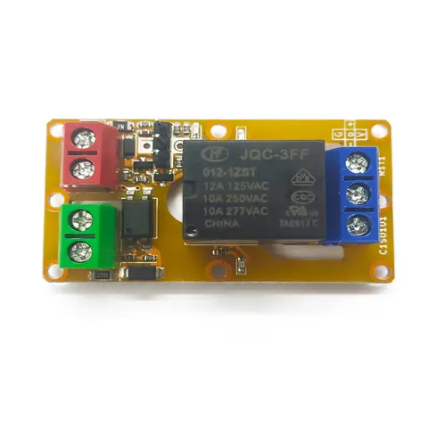
A1J0101 Economical Input Amplifier Module
Optocoupler-isolated input amplifier that turns a low-voltage signal into a 250V AC / 10A relay output.
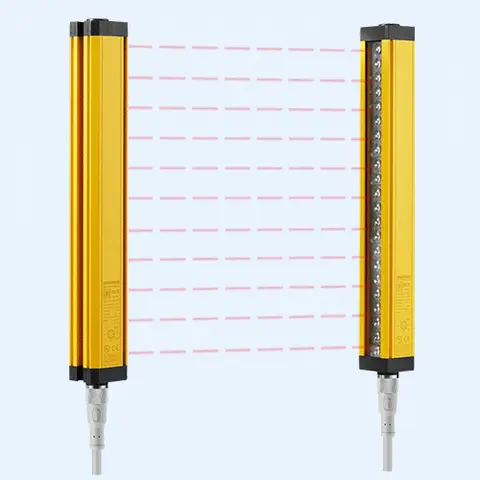
DCE Automation Safety Light Curtain
Compact through-beam safety light curtain in a 30 x 30 mm housing: 10/20/30/40 mm beam pitch, up to 72 beams, 0.3-3 m or 0.3-6 m sensing distance, NPN/PNP output. Catalogue-stated Type 4 design basis; confirm exact safety-document scope.
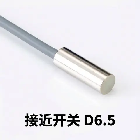
D6.5 Series Inductive Proximity Sensors (Ultra-Short 18mm / Y-Type / 35mm / 45mm)
6.5mm-diameter inductive proximity sensors for tight-clearance mounting where M8 sensors won't fit.
Related Products in LiDAR Scanners
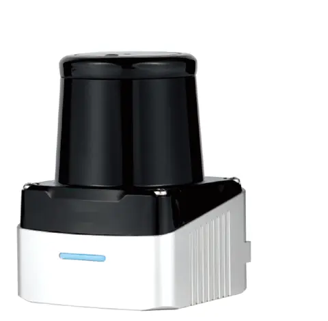
DLD-100D Single-Line TOF Scanning LiDAR
Single-line TOF scanning LiDAR with up to 100 m range, model-dependent 280°/360° coverage, and a 100 Hz / 0.32° DLD-100DP option.
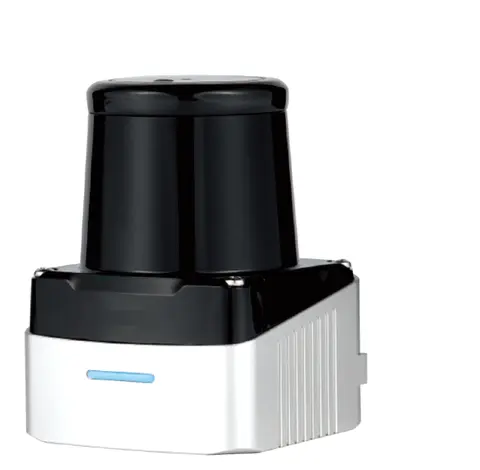
DLD-50D 2D TOF LiDAR for Navigation & Mapping (50 m)
50 m-range 2D TOF LiDAR for mobile robot navigation and mapping — ±20 mm repeatability, 280° FoV, Ethernet output.
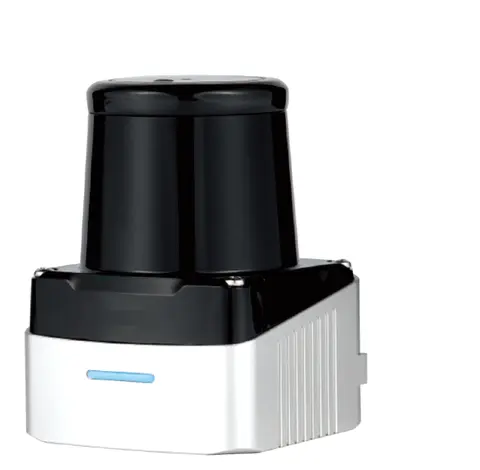
DLD-50G 2D Single-line LiDAR (Diffuse-remission Measuring Type)
2D single-line laser scanner measuring diffuse-remission distance off natural surfaces, no reflector needed.
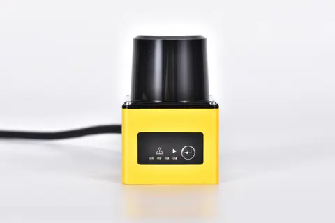
DLD05A3 2D TOF Obstacle-avoidance LiDAR (5 m)
2D TOF LiDAR with NPN/PNP switching outputs that wires like a photoelectric sensor — no protocol stack, no SDK.