
A1J0101 Economical Input Amplifier Module
Optocoupler-isolated input amplifier that turns a low-voltage signal into a 250V AC / 10A relay output.
 🔍 Click to enlarge · 1/8
Technical Specifications
| Type | Optocoupler-isolated input amplifier, relay or transistor output |
|---|---|
| Supply voltage options | 5V / 9V / 12V / 18V / 24V DC (default M31 = 12V relay output) |
| Supply voltage operating range | 5V DC: 4.8-5.2V; 9V DC: 8.5-11V; 12V DC: 11-14V; 18V DC: 16-20V; 24V DC: 20-28V |
| Supply voltage absolute maximum | 5V: DC 5.3V; 9V: DC 11.5V; 12V: DC 15V; 18V: DC 22V; 24V: DC 30V |
| Power supply ripple | < 1Vp-p |
| Supply current | < 50mA (typical 40mA when relay is energized) |
| Self-resettable fuse | DC 30V, 500mA |
| Input stress (normal) | DC 0-30V |
| Input stress (absolute maximum) | DC 50V |
| Input isolating voltage (normal) | < 250V |
| Input isolating voltage (absolute maximum) | DC 1000V, 60s (type test) |
| Output stress, relay type (normal) | DC 30V or AC 0-220V, 8A |
| Output stress, relay type (absolute maximum) | AC 250V, 10A |
| Output stress, transistor type (normal) | DC 12-48V, 8A |
| Output stress, transistor type (absolute maximum) | DC 55V, 10A |
| Output isolating voltage, relay type | < 250V (normal); DC 1000V, 60s (absolute maximum, type test) |
| Output isolating voltage, transistor type | < 130V (normal); DC 250V, 60s (absolute maximum, type test) |
| Relay mechanical life | > 100,000 operations (> 10,000 under heavy load) |
| Operating temperature | -20 to 60°C |
| Storage temperature | -40 to 85°C |
| ESD immunity | IEC 61000-4-2: 6kV, discharge on all terminals - module functions normally |
| EFT immunity | IEC 61000-4-4: 2kV/5kHz/2min - normal operation; 4kV/5kHz/2min - relay may jitter, no permanent damage |
| Surge immunity | IEC 61000-4-5: 1kV to ground on power terminals - no permanent damage (by design) |
| Creepage distance | > 6.05mm measured (requirement > 6mm), pollution degree 3, material group IIIa/IIIb |
| Electrical clearance | > 2.2mm measured (requirement > 2mm) |
| PCB dimensions | 55 x 30mm (tolerance ±5%) |
| Mounting hole spacing | 49mm (vertical) x 24.5mm (horizontal) |
| Terminal pitch | 5.08mm |
| Optional enclosure dimensions | approx. 35.5 x 60.5 x 22mm |
| Terminals | 7 screw terminals, 1 jumper header, 3 LED indicators |
Overview
The A1J0101 is an optocoupler-isolated input amplifier module for industrial control panels and OEM system integrators. It accepts a low-voltage signal on its optocoupler input and drives a single isolated relay output, letting a PLC, sensor, or control signal safely switch a higher-power load without direct electrical contact between the control side and the load side.
Input and output isolation is rated up to 1000V DC (60s type test), while the relay output switches DC 30V or AC 0-220V at 8A under normal operating conditions, with an absolute maximum of AC 250V, 10A. The module accepts 5V, 9V, 12V, 18V or 24V DC supply at under 50mA, and its input trigger polarity (high-level or low-level operation) is selectable with an on-board jumper.
Features & Benefits
An Isolator and a Power Relay on One 55 x 30mm Board
A DC 1000V (60s type test) optocoupler input and a relay contact rated AC 250V / 10A absolute maximum sit on a single 55 x 30mm PCB with 5.08mm screw terminals. One part number, one set of wiring and one mounting position replace a separate signal isolator plus an interposing relay - the cheapest honest way to get a low-voltage signal to switch a mains-side load.
One Jumper Cap Sets Polarity - or Forces the Relay On or Off
Terminal 7 is a 5-pin header marked V, G, +, - and o. Cap 'o' to '+' for high-level operation (relay makes on signal), or 'o' to '-' for low-level operation, so one stock module suits sourcing and sinking sensors with no redesign; the relay makes whenever 'o' sees more than 2V. Cap 'o' to 'V' or 'G' instead and the relay is held permanently made or broken for commissioning and bypass - and because the V and G pads ship unpopulated and must be soldered, a stray cap cannot defeat your logic in normal use.
One Board, Two Independent Modules When You Need Them
Remove the jumper cap and the optocoupler input and the relay output become two non-interfering functions: a standalone DC 1000V isolated input and a standalone isolated relay output. In a mixed panel that means one board can serve two unrelated circuits, cutting board count and terminal wiring in cost-sensitive volume builds.
EFT Headroom of 2x the Industrial Requirement, and a Fuse You Never Replace
The module runs normally through 2kV/5kHz/2min EFT - twice the 1kV that IEC 61000-6-2-2016 asks of basic industrial equipment - takes 6kV ESD on every terminal, and survives 4kV EFT and a 1kV surge without permanent damage. Reverse-polarity protection and a self-resettable DC 30V / 500mA fuse mean a miswired supply or a brief overload costs you a power cycle, not a site visit with a spare fuse.
Creepage Slots Cut Into the PCB, With Measured Margin
The high-voltage side is separated by creepage slots routed into the PCB: measured creepage from relay terminal to logic side is more than 6.05mm against a 6mm requirement, and clearance more than 2.2mm against 2mm, at pollution degree 3 with material group IIIa/IIIb. The margin is measured on the real board, not just drawn. Certification documents are available on request.
Matches Your Existing DC Rail and Barely Loads It
Five supply versions - 5V, 9V, 12V, 18V and 24V DC, each with its own working window (the 12V type accepts DC 11-14V) - draw less than 50mA, typically 40mA with the relay energized. That is light enough to hang several modules off a small PLC or sensor supply, and custom supply voltages are available. Undesignated orders ship as M31: 12V supply, relay output.
Three LEDs and Both Contacts Make Commissioning Fast
A green power LED, a yellow input LED and a blue action LED let you tell 'no supply' from 'no signal' from 'relay not pulling in' at a glance, without a meter. NO and NC are both brought out to screw terminals, so a break-on-signal function needs a wire move rather than a different part. Note that in low-level operation the yellow input indicator stays illuminated by design.
Transistor Output Version for Inductive Loads and High Cycle Counts
Order the transistor type ([dd] second digit = 2) for an open-drain output rated 12-48V DC / 10A with a 10A freewheeling diode built in, so it drives heavy-duty electromagnets and motors directly with no contact to wear out. Because transistors are more sensitive than relays, plan power sequencing: with the input unconnected, the output may pulse for about 100ms at power-up or power-down.
Applications
Models & Ordering Information
Base Model
PDF & 3D CAD Downloads
Browse all downloadsA1J0101 Economical Input Amplifier Module User Manual
Confirm the document and CAD file match the exact ordered version before installation or mechanical design. Contact us if your model is not listed.
How to Select
- Default configuration is A1J0101M31 (12V DC supply, relay output), which covers most general-purpose applications.
- Choose the supply voltage suffix (5/9/12/18/24V) to match your control system's DC rail.
- For controlling mains-voltage loads, use the enclosed version; without an enclosure the module is only recommended for safety extra-low voltage (0-36V) control.
- Choose the transistor output version for inductive loads, higher switching frequency, or longer contact-free life, and add power sequencing to avoid the brief power-up/power-down pulse.
- Choose the relay output version for pure on/off switching where a passive dry contact or mains-voltage load is required; NO and NC contacts are both available.
- Set the input trigger polarity with the on-board jumper to match your sensor or control signal's high-level-active or low-level-active logic.
📘 Need the full method? NPN vs PNP Sensor Outputs Explained
When NOT to specify the A1J0101 — and what to use instead
Application needs a delay or timer function
Why not: A1J0101 has no timing element at all — it is an instantaneous optocoupler-input-to-relay amplifier: signal present, relay makes; signal removed, relay breaks. No delay range is published in its parameters because there is none.
Use instead: B2J0101 (power-up delay, 2-30 s) or B2J0201 (trigger delay, 2-30 s). For more modes or longer ranges, B2J0601 or E4J0101.
Switching a load above the output's rated stress
Why not: The relay output's absolute maximum is AC 250 V / 10 A, with normal operation at DC 30 V or AC 0-220 V at 8 A. The transistor version's absolute maximum is DC 55 V / 10 A, normal DC 12-48 V at 8 A. Absolute maximum is a survival limit, not an operating point.
Use instead: Use the A1J0101 contact as a pilot / interposing relay to drive an external contactor sized for the actual load.
Switching AC mains on the bare board with no enclosure
Why not: The manual recommends the caseless board only for safe extra-low voltage control, 0-36 V. Mains-level switching is intended for the version fitted with the optional enclosure.
Use instead: Order the module with the optional 35.5 x 60.5 x 22 mm enclosure fitted before wiring to AC mains.
A machine-safety stop or interlock function
Why not: A1J0101 is a general-purpose optocoupler-isolated input amplifier with an ordinary relay or transistor output. It has no forcibly-guided contacts, no EDM feedback, and no Type / SIL / PL rating.
Use instead: DA31 Emergency-Stop Safety Relay Module or DQSRN Safety Relay Module.
High-cycle switching of an inductive DC load such as a solenoid or small motor
Why not: The relay version's mechanical life is rated above 100,000 operations but only above 10,000 operations under heavy or inductive load. Contact wear becomes the limit long before the mechanical figure on frequent inductive duty.
Use instead: The transistor-output variant, which has no contacts to wear and includes a 10 A freewheeling diode.
Several isolated I/O points on one board or one bus
Why not: A1J0101 is strictly single-channel: one optocoupler input and one relay or transistor output per board.
Use instead: B2J0302 for a single networked point, or the D3J01xx / D3J02xx / D3J03xx multi-channel MODBUS I/O modules for several points on one bus.
Specifications we do not publish yet
We only publish a figure once we are confident it is true. The items below are still being validated through further testing and real-world customer feedback, so for now we would rather leave them open than guess. If one of them matters to your design, ask us for the latest validated status.
- Electrical (load-switching) contact life under the rated 8 A load, as distinct from the published mechanical life.
- Relay brand and model number.
- Ingress protection (IP) rating of the bare board and of the optional enclosure.
- MTBF.
- Operating and storage relative humidity range.
- Terminal wire gauge and screw torque.
- Vibration and mechanical shock resistance.
- Certification status. The manual records a CCC application as in progress, not granted — we do not claim it. Certification documents are available on request.
Frequently Asked Questions
Is the A1J0101 a safety relay or a standard signal-isolation relay module?
What supply voltages does the A1J0101 support?
How do I set the input trigger polarity?
What load can the relay and transistor outputs switch?
Can the optocoupler input and relay output be used independently?
Why does the transistor-output version briefly pulse at power-up?
Does the A1J0101 meet industrial EMC and safety requirements?
Related Categories and Example Products
Explore other functions that may be needed in a machine or line. The products below are category examples, not pre-validated electrical or safety combinations. Confirm each interface and application separately: Proximity Sensors · Photoelectric Sensors · Laser Distance Sensors
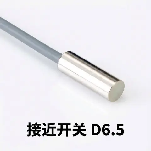
D6.5 Series Inductive Proximity Sensors (Ultra-Short 18mm / Y-Type / 35mm / 45mm)
6.5mm-diameter inductive proximity sensors for tight-clearance mounting where M8 sensors won't fit.
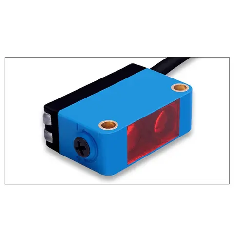
BGS-CX441 / BGS-CX442 Background Suppression Photoelectric Sensor
Wire-adjustable BGS sensor with 2 mm or 15 mm spot, 10-300 mm range, published black/white differential distance.
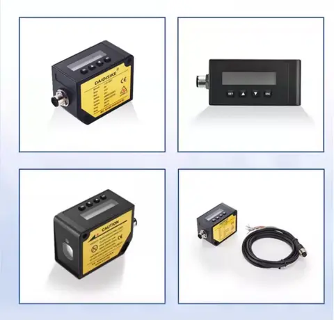
DDA-Y & DDB-Y Industrial Laser Distance Sensor (Phase-Shift)
Phase-shift laser distance sensors: 0.2-100 m range, millimeter accuracy, RS485 Modbus RTU, switching or analog output.
Related Products in Relay & Timer Modules
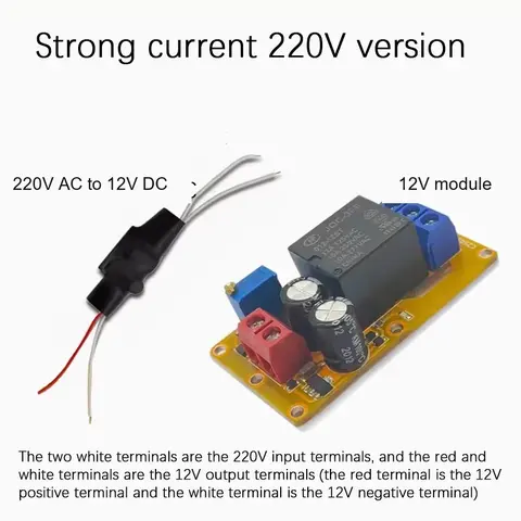
B2J0101 Economical Power-up Delay Module
Low-cost power-up delay relay module with a 2-30 second adjustable delay and no trigger input required.
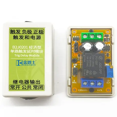
B2J0201 Economical Trigger Delay Module
Level-triggered delay relay module with jumper-selectable high/low trigger and a 2-30s adjustable delay.
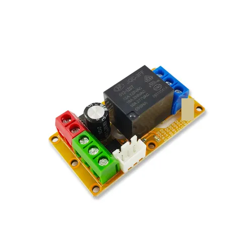
B2J0302 Enhanced Single MODBUS-485 I/O Module
Enhanced single-channel MODBUS-RTU/RS-485 I/O module: 1 digital input, 2 analog inputs, 1 relay or transistor output, AT command support and a 5V sensor supply — the successor to the discontinued B2J0301.
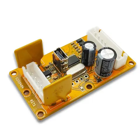
B2J0401 MODBUS Analog/Digital I/O Module
Economical MODBUS-RTU/RS-485 module: 4 analog/digital inputs plus 2 MOSFET PWM/PTO outputs.