
B2J0101 Economical Power-up Delay Module
Low-cost power-up delay relay module with a 2-30 second adjustable delay and no trigger input required.
 🔍 Click to enlarge · 1/7
Technical Specifications
| Delay Method | Power-up delay (countdown starts the instant power is applied; no trigger input) |
|---|---|
| Delay Range | 2 - 30 seconds, adjustable via on-board potentiometer (clockwise to increase, counter-clockwise to decrease) |
| Core IC | NE555 |
| Output | Single relay, NO/NC (transistor output variant also available) |
| Supply Voltage | 5/9/12/18/24V DC (normal operating range 4.8-5.2 / 8.5-11 / 11-14 / 16-20 / 20-28V respectively) |
| Supply Ripple | < 1Vp-p |
| Supply Current | < 50mA (typical 40mA when the relay is energized) |
| Output Stress (normal operating) | Relay type: DC 30V or AC 0-220V, 8A; Transistor type: DC 12-48V, 8A |
| Output Isolation Voltage (normal operating) | Relay type < 250V; Transistor type < 130V |
| Absolute Max Supply Voltage | DC 5.3 / 11.5 / 15 / 22 / 30V for the 5/9/12/18/24V versions respectively |
| Self-Recovering Fuse | DC 30V, 500mA |
| Absolute Max Output Stress | Relay type: AC 250V, 10A; Transistor type: DC 55V, 10A |
| Absolute Max Output Isolation Voltage (type test) | Relay type: DC 1000V, 60s; Transistor type: DC 250V, 60s |
| Relay Mechanical Life | > 100,000 operations (> 10,000 under heavy load) |
| Operating Temperature | -20 ~ 60°C |
| Storage Temperature | -40 ~ 85°C |
| ESD Immunity (IEC61000-4-2) | 1kV all terminals: normal operation; 2kV: no permanent damage |
| EFT Immunity (IEC61000-4-4) | 500V / 5kHz / 2min: normal operation (delay time may shift slightly); 1kV: no permanent damage |
| Surge Immunity (IEC61000-4-5) | 1kV, power terminals to ground: no permanent damage (by design) |
| Creepage Distance / Clearance | Measured > 9.2mm creepage (> 6mm required) / > 2.2mm clearance (> 2mm required), pollution degree 3 |
| PCB Dimensions | 55 x 30mm (L x W), tolerance ±5% |
| Mounting Hole Spacing | 49mm (top-bottom) x 24.5mm (left-right) |
| Terminal Pitch | 5.08mm |
| Terminals & Controls | 5 screw terminals + 1 adjustment potentiometer + 2 LED indicators |
Overview
B2J0101 is a power-up delay relay module built for engineers and OEM integrators who need a device that automatically switches a load on after a fixed interval once power is first applied, with no external trigger signal, button press, or control-line wiring required. It can be supplied from 5V, 9V, 12V, 18V or 24V DC, is built around an NE555 timing core, and the countdown begins the instant power is applied.
The delay is adjustable from 2 to 30 seconds using an on-board potentiometer (clockwise increases the delay, counter-clockwise decreases it), giving field technicians and production-line staff a simple mechanical setting with no programming or host computer required. The single relay output brings out both normally-open (NO) and normally-closed (NC) contacts, rated up to 250V AC / 10A as an absolute maximum (8A at AC 0-220V or DC 30V under normal operating conditions), with a supply current below 50mA (typical 40mA when the relay is energized).
Features & Benefits
No trigger input to wire - the delay starts the moment power arrives
B2J0101 has five screw terminals and nothing else to connect: supply positive to terminal 4, supply negative to terminal 3, and the load loop through the NO (0) and COM (1) contacts. There is no trigger terminal, no signal cable to run back to a sensor or PLC, and no polarity or level convention to get wrong, so an installer can turn a bare board into a working delay circuit in a couple of minutes.
NE555 timing core with a screwdriver-set 2-30 s potentiometer
The delay is set by turning the on-board knob (terminal 5) - clockwise to increase, counter-clockwise to decrease - anywhere from 2 to 30 seconds. No programming, no software, no host controller and no DIP-switch table: production-line staff can dial in the timing on the bench, and the blue action indicator (6) plus green power indicator (7) let them confirm the setting by eye without a meter.
Change-over contact means one module covers delay-on and delay-off
Both NO and NC contacts are brought out. The NO contact (0-1) is open at power-up and closes when the delay expires, which delays a load on. The NC contact (2-1) is closed at power-up and opens when the delay expires, so the same board can instead run a load for 2-30 seconds after power-up and then cut it - a purge fan, a pre-charge resistor, a start-up bypass - without adding any parts.
Isolated relay output that switches real loads, not just logic
The single relay is rated AC 250 V / 10 A as an absolute maximum, with a normal operating output stress of AC 0-220 V or DC 30 V at 8 A, and an output isolation type-tested to DC 1000 V for 60 s. The load circuit is galvanically separated from the module's timing side, so the same 12 V board can switch a mains-fed heater (with the optional case fitted) or a 24 V DC valve. Without a case, keep the switched circuit to safe voltages of 0-36 V.
Runs off the rail the machine already has, at under 50 mA
5 V, 9 V, 12 V, 18 V and 24 V supply versions are available (default ordering configuration M31 is 12 V with relay output), each with a generous window - the 12 V version accepts DC 11-14 V, the 24 V version DC 20-28 V. Supply current is below 50 mA, typically 40 mA with the relay energized, so the module can hang off a spare auxiliary output or PLC supply instead of forcing a bigger power supply into the panel. Other voltages are available on request.
Protection built in for the abuse a field board actually sees
Reverse supply polarity, overcurrent (a self-recovering DC 30 V / 500 mA fuse that resets itself instead of needing a service call), electrostatic discharge, electrical fast transient and surge protection are all on board. Tested to IEC61000-6-1-2016 light-industry requirements: 1 kV ESD on all terminals with normal operation and 2 kV with no permanent damage; 500 V / 5 kHz / 2 min EFT with normal operation; 1 kV surge from power terminals to ground with no permanent damage.
Creepage slots milled to beat the safety requirement by 50 percent
The PCB carries creepage slots isolating the high-voltage relay side from the logic side. Measured creepage is above 9.2 mm against the 6 mm required by IEC60950 at pollution degree 3, and electrical clearance is above 2.2 mm against a 2 mm requirement - margin that matters on a board this small, where the easy route would have been to meet the minimum and stop. Certification documents are available on request.
Optional transistor output for silent, high-cycle and inductive loads
A transistor-output variant replaces the relay with an open-drain stage rated DC 12-48 V (8 A under normal operating conditions, 10 A absolute maximum) with a 10 A flyback diode fitted, so it drives inductive loads such as electromagnets and motors directly. It is silent and has no contacts to wear, which suits duty that would eat through the relay's 100,000-operation mechanical life (over 10,000 under heavy load).
Applications
Models & Ordering Information
B2J0101 Power-up Delay Module
PDF & 3D CAD Downloads
Browse all downloadsB2J0101 Economical Power-up Delay Module User Manual
Confirm the document and CAD file match the exact ordered version before installation or mechanical design. Contact us if your model is not listed.
How to Select
- Bare-board supply, enclosure and DIN-rail mounting are ordering options for this B2J/E4J module. Specify what is included on the quotation; do not assume an enclosure or mounting kit is supplied as standard.
- Choose B2J0101 when the application only needs a delay that starts automatically at power-on, with no external trigger signal or button — it has the simplest wiring and lowest cost of the B2J01 delay family.
- If the delay instead needs to be started by an external level signal or pushbutton (e.g. a sensor output or switch), with selectable high/low trigger polarity, choose B2J0201 (level-triggered delay) instead.
- If the application needs multiple delay modes (delay-off, cyclic on/off, edge-triggered, self-latching), delay ranges in seconds/minutes/hours, higher timing precision, or voltage-threshold detection, choose B2J0601 (multi-mode delay) instead.
- Confirm the required supply voltage: B2J0101 covers 5V, 9V, 12V, 18V and 24V DC, with the default ordering code corresponding to the 12V relay-output configuration; other voltages are available on request.
- Select by normal operating ratings, load type and isolation: relay output is listed at DC 30V or AC 0-220V / 8A; the transistor variant at DC 12-48V / 8A. The 10A figures are absolute maxima, not continuous design ratings. Check inductive-load suppression and the exact output version.
- If the board will be used without a case, limit the controlled circuit to a safe extra-low voltage (0-36V); a case is needed if the module will switch AC mains.
- Check the operating temperature range (-20 to 60°C) and confirm it matches the installation environment, especially for automotive or outdoor-adjacent placements.
📘 Need the full method? NPN vs PNP Sensor Outputs Explained
When NOT to specify the B2J0101 — and what to use instead
The delay must be started by a sensor, switch or PLC signal rather than by power-on
Why not: B2J0101 has no trigger input terminal. The countdown starts the instant power is applied and cannot be held off, restarted or retriggered by any external signal.
Use instead: B2J0201 for level-triggered delay, or B2J0601 for multi-mode delay with edge triggers.
A delay shorter than 2 s or longer than 30 s
Why not: The on-board potentiometer covers a 2-30 second window only. There is no minute or hour range and no sub-second setting.
Use instead: B2J0601 (0-255 units in seconds / minutes / hours) or E4J0101 (0-999 x selectable unit from 10 ms to 10 h).
A panel where large motors, contactors or other strong EMI sources share the supply
Why not: B2J0101 is tested to IEC 61000-6-1 light-industry levels (500 V EFT with normal operation), not the 1 kV EFT of the IEC 61000-6-2 industrial requirement.
Use instead: Add a supply-line EFT filter or an EFT-resistant isolated supply with a cord under 3 m, or step up to E4J0101, which is measured at 2 kV EFT.
Switching a load beyond the output's rated stress
Why not: Absolute maximum is AC 250 V / 10 A (relay type) or DC 55 V / 10 A (transistor type). Normal operating stress is 8 A at AC 0-220 V / DC 30 V, or 8 A at DC 12-48 V.
Use instead: Drive an external contactor sized for the load from the B2J0101 contact rather than switching the load directly.
A safety-related power-up delay such as a guard-release or interlock timer
Why not: It is a commercial-grade timer relay with no forcibly-guided contacts and no safety rating.
Use instead: DA31 Emergency-Stop Safety Relay Module or DQSRN Safety Relay Module.
The delay setting must be numerically precise, remotely readable or logged
Why not: The delay is set by turning an analog potentiometer, with only an action LED and a power LED. There is no digit display and no digital readback of the set value.
Use instead: E4J0101, which has a 4-digit display and can be calibrated to 0.1% over USB.
Specifications we do not publish yet
We only publish a figure once we are confident it is true. The items below are still being validated through further testing and real-world customer feedback, so for now we would rather leave them open than guess. If one of them matters to your design, ask us for the latest validated status.
- Electrical (load-switching) contact life under the rated 8 A load, as distinct from the published mechanical life.
- Relay brand and model number.
- Ingress protection (IP) rating.
- MTBF.
- Quantified temperature drift of the delay circuit. The manual notes EFT exposure may shift the delay slightly but gives no figure.
- Operating and storage relative humidity range.
- Terminal wire gauge and screw torque.
- Certification status — the manual states none. Certification documents are available on request.
Frequently Asked Questions
What does the B2J0101 power-up delay relay module do?
What supply voltages does B2J0101 support?
How do I adjust the delay time?
Can B2J0101 switch AC mains voltage?
What is the maximum load the relay output can switch?
Is a transistor output version available?
What protection features does B2J0101 have?
How long does the relay last?
What is the difference between B2J0101, B2J0201 and B2J0601?
Can you provide certification documents for B2J0101?
Related Categories and Example Products
Explore other functions that may be needed in a machine or line. The products below are category examples, not pre-validated electrical or safety combinations. Confirm each interface and application separately: Proximity Sensors · Photoelectric Sensors · Laser Distance Sensors

D6.5 Series Inductive Proximity Sensors (Ultra-Short 18mm / Y-Type / 35mm / 45mm)
6.5mm-diameter inductive proximity sensors for tight-clearance mounting where M8 sensors won't fit.
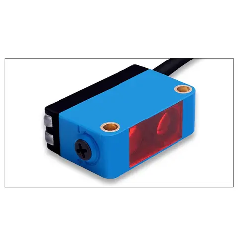
BGS-CX441 / BGS-CX442 Background Suppression Photoelectric Sensor
Wire-adjustable BGS sensor with 2 mm or 15 mm spot, 10-300 mm range, published black/white differential distance.
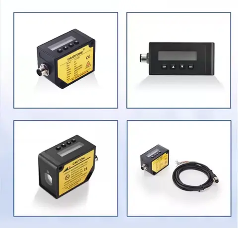
DDA-Y & DDB-Y Industrial Laser Distance Sensor (Phase-Shift)
Phase-shift laser distance sensors: 0.2-100 m range, millimeter accuracy, RS485 Modbus RTU, switching or analog output.
Related Products in Relay & Timer Modules
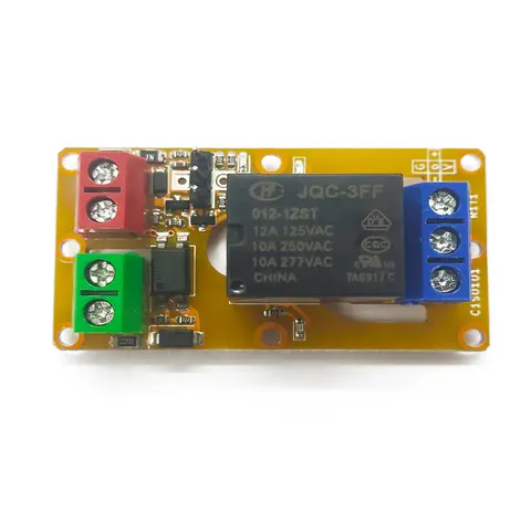
A1J0101 Economical Input Amplifier Module
Optocoupler-isolated input amplifier that turns a low-voltage signal into a 250V AC / 10A relay output.
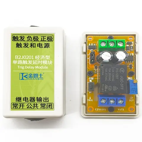
B2J0201 Economical Trigger Delay Module
Level-triggered delay relay module with jumper-selectable high/low trigger and a 2-30s adjustable delay.
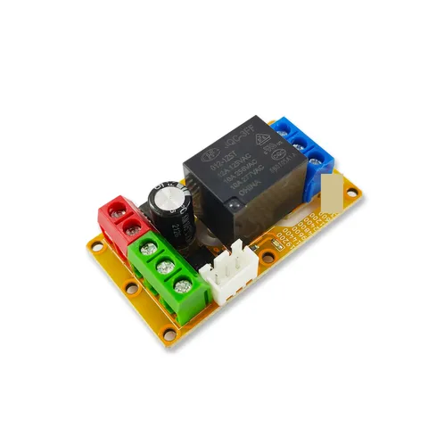
B2J0302 Enhanced Single MODBUS-485 I/O Module
Enhanced single-channel MODBUS-RTU/RS-485 I/O module: 1 digital input, 2 analog inputs, 1 relay or transistor output, AT command support and a 5V sensor supply — the successor to the discontinued B2J0301.
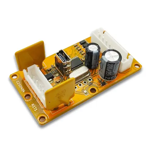
B2J0401 MODBUS Analog/Digital I/O Module
Economical MODBUS-RTU/RS-485 module: 4 analog/digital inputs plus 2 MOSFET PWM/PTO outputs.