
DDA-Y & DDB-Y Industrial Laser Distance Sensor (Phase-Shift)
Phase-shift laser distance sensors: 0.2-100 m range, millimeter accuracy, RS485 Modbus RTU, switching or analog output.
 🔍 Click to enlarge · 1/10
Technical Specifications
| Measurement Principle | Phase-shift |
|---|---|
| Output (DDA-Y) | Two switching outputs (NPN sinking wiring documented, ≤36V/0.5A) + menu-selectable RS232/RS485; Modbus RTU over RS485. No analog output. Confirm PNP requirements before ordering. |
| Output (DDB-Y) | Two switching outputs (NPN sinking wiring documented) + selectable analog output (0-5V/0-10V/4-20mA/0-20mA/0-24mA) + RS232/RS485. Confirm PNP requirements before ordering. |
| Measuring Range | 0.2 m starting distance, rated maximum 10 / 20 / 30 / 50 / 100 m |
| Measurement Accuracy | ±(2 mm + distance × 1/10000) at speed level 1; verify required accuracy at faster settings |
| Resolution | 1 mm |
| Response/Sampling Frequency | Specification table: 1-40 Hz. Speed menu: 5 levels, approximately 10 Hz at level 1 and 40 Hz at level 5; confirm rate and allowed error together. |
| Communication / Networking | Modbus RTU, supports 64 units on one bus |
| Laser | 660±15 nm, ≤1 mW, Class II (visible red) |
| Laser Spot Size | ⌀6 mm @1 m, ⌀8 mm @10 m, ⌀12 mm @20 m, ⌀16 mm @30 m |
| Analog Output Accuracy (DDB-Y) | Voltage output error 0.2%+0.5mV; current output error 0.2%+0.005mA |
| Switching Output Rating | Two NPN sinking transistor channels; rating ≤DC36V/0.5A. Keep operating load current below 500mA as specified in the wiring note. |
| Operating Voltage | DC15-30V |
| Power Consumption | <3W |
| Protection Rating | IP67 |
| Connector | M12 8-pin |
| Cable and Accessories Reference | Manual checklist: one approximately 2 m M12 8-pin cable, manual, box, one metal-film resistor and two mounting screws with one sensor. Confirm actual included items in the quotation. |
| Over-temperature Protection | >70°C shutdown, resumes below 70°C |
| Working Temperature | -10°C to 50°C |
| Storage Temperature & Humidity | -20°C to 60°C, 20%-85% RH |
| Housing Material | Die-cast zinc alloy |
| Dimensions | 88.45 × 40 × 59.3 mm (including connector) |
Overview
DDA-Y and DDB-Y are industrial-grade phase-shift laser distance sensors that project a visible red laser (Class II, 660±15 nm) onto a target surface and calculate distance from the returned signal, for non-contact position, displacement, thickness, and distance measurement. Both series come in five range variants (10/20/30/50/100 m) sharing the same housing, display, and communication protocol. DDA-Y outputs digital data plus two switching outputs only; DDB-Y adds a configurable analog output (voltage or current).
They are intended for machine builders, system integrators, and plant engineers who need reliable long-range position feedback for automation, material handling, or structural monitoring, and who want to wire the sensor directly into a PLC via switching outputs, an analog loop, or an RS-485/Modbus RTU network. Measurement error is ±(2 mm + d × 1/10000) at speed level 1 with 1 mm resolution, and up to 64 units can share one RS-485 bus using Modbus RTU.
DDA-Y or DDB-Y: Match the Controller Input
Select the output your receiving instrument needs, then choose the distance range. DDB-Y adds an analog channel; it is not specified as the more accurate series.
| Purchase requirement | DDA-Y | DDB-Y |
|---|---|---|
| Serial distance data and two switching channels | Available | Available |
| Analog distance signal | No analog output | Select 0-5 V, 0-10 V, 4-20 mA, 0-20 mA or 0-24 mA |
| Current and voltage simultaneously | Not applicable | Not supported; select one analog mode |
| Maximum range options | 10 / 20 / 30 / 50 / 100 m | 10 / 20 / 30 / 50 / 100 m |
Both families start at a rated 0.2 m. Provide the nearest and farthest target positions across the complete movement. For switching inputs, the operating manual documents NPN sinking outputs; confirm the ordered hardware and receiving input before specifying PNP compatibility.
Confirm the Target and Mounting Version
The supplied documents do not define a complete standard target or reflectivity condition for the 100 m rating. They note that strong sunlight and temperature changes can increase measurement error, and that a target reflector can improve performance. Send the actual material, colour, finish, target area and angle for assessment. Describe transparent or glossy surfaces, liquid or foam, and dust or moisture as application conditions to test; their suitability is not established by the range code.
The current longitudinal mounting-hole spacing is confirmed as 46.78 mm. The supplied series CAD is a layout reference, not an approved drawing for every ordered version. Before making a bracket, check the drawing revision against the ordered hardware and allow room for the connector and cable.
Prepare a Quotation and Sample Acceptance Plan
| Item | Details to provide |
|---|---|
| Measurement | Required distance span, allowed error, target movement and update time |
| Target and site | Target photograph or sample; surface, light exposure, temperature, dust and moisture |
| Controller | Input-module model, supply, serial interface or analog standard, and switching requirements |
| Supply scope | Quantity, delivery country, cable and mounting requirements, and required documents |
Ask the quotation to identify the full model and included accessories. For sample approval, compare readings at known near, middle and far positions using the intended speed setting. Verify switching transitions, DDB-Y analog scaling where used, and the controller's interpretation of serial data. Record the configuration and acceptance limits before ordering the production quantity.
A position, level or thickness application also needs a defined reference arrangement. Agree that arrangement during evaluation; an ordinary distance output does not establish a personnel-protection function.
Match Accuracy, Update Speed and Target Conditions
| Condition | What the operating manual states | Purchase implication |
|---|---|---|
| Measurement error | ±(2 mm + d × 1/10000), at speed level 1 | Use the intended speed setting in the error budget; 1 mm resolution is not ±1 mm accuracy |
| Speed setting | Five levels; level 1 approximately 10 Hz, level 5 approximately 40 Hz; accuracy reduces as speed increases | Agree the required update rate and allowed error together, then verify on the supplied unit |
| Frequency-table wording | The specification table separately lists 1-40 Hz | The table and speed-menu wording are not a complete rate/error matrix; confirm the selected configuration |
| Light and temperature | Strong sunlight and large ambient-temperature changes can increase error; a target reflector may improve results | Provide sun direction, temperature variation and target conditions; no numeric lux limit is supplied |
| Target reflectivity | No complete reflectivity percentage/standard-target condition for the 100 m rating is supplied | Test the actual surface, size and angle; do not guarantee 100 m on every target |
Check the Package Against the Quotation
The operating manual's package checklist lists the items below. It is a document reference, not a promise that every range code, custom configuration or quotation includes exactly the same accessories.
| Item listed in the manual | Listed quantity or description |
|---|---|
| Sensor | 1 unit |
| M12 8-pin connector cable | 1 cable, approximately 2 m |
| Instruction manual | 1 copy |
| Box | 1 |
| Metal-film resistor | 1; the checklist does not identify it as the RS-485 terminating resistor |
| Mounting screws | 2 |
Ask the quotation to confirm cable length, connector version, screws/bracket requirements, any reflector and the resistor specification. A reflector is mentioned as a measurement aid, not listed in this package checklist. Match the manual's 8-pin assignment to the supplied ordered version before wiring.
Compare the Measurement Task Before Specifying
Browse the laser distance sensor catalogue for the available families. Review DSK-CG configurations when comparing range and output variants, or DDK-F specifications for another long-range package. Validate each model against its own target, interface and mounting requirements.
For short-stroke dimensional inspection, compare the DDK-G displacement models. If you need coverage across a plane instead of a distance along one beam, the 2D LiDAR selection guide explains the available scanning and output choices.
Features & Benefits
Millimeter-class accuracy out to 100 m
Measurement error is ±(2 mm + d × 1/10000) at speed level 1, with 1 mm resolution; at a 50 m reading this works out to roughly ±7 mm. Verify the required error and update rate together before using the readings in a position-control system; resolution alone does not establish positioning accuracy.
Five range options, one common platform (0.2-10/20/30/50/100 m)
DDA-Y10/20/30/50/100 and DDB-Y10/20/30/50/100 all start measuring from as close as 0.2 m and share the same housing, display, buttons, and communication interface, so customers select the range they actually need without switching product families.
RS-485 Modbus RTU multi-drop networking, up to 64 units on one bus
All sensors share a single twisted-pair RS-485 bus (station addresses 1-64), reducing wiring and PLC analog input channel count for multi-point applications such as multi-bay level monitoring or several cranes on one line. A 120 Ω/8 W terminating resistor is recommended at the bus end if communication is unstable.
DDB-Y offers five menu-selectable analog output standards
DDB-Y can be set via the on-device menu to output 0-5 V, 0-10 V, 4-20 mA, 0-20 mA, or 0-24 mA, with a stated output accuracy of 0.2%+0.5 mV (voltage) or 0.2%+0.005 mA (current). The minimum and maximum distances mapped to the output span are configurable. Check the receiving input, wiring and scaling before changing modes; voltage and current are not available simultaneously.
Two switching outputs for process threshold signals
The manual documents two NPN sinking transistor outputs, rated up to DC 36 V/0.5 A. Each has independently configurable normally-open/normally-closed logic and a distance threshold window. Match the receiving circuit and load to the manual. These are ordinary process outputs, not safety-rated stop or personnel-protection outputs.
On-board 128×32 display and 4-button menu — no PC needed for setup or daily reading
The unit shows station number, live measured distance, and unit directly on a 128×32 dot-matrix screen, and every setting (speed level, switching thresholds, analog range, communication parameters, language) is configured via 4 buttons without connecting a laptop; the backlight auto-turns-off after 30 minutes or can be set to stay always on.
Built-in over-temperature protection (auto shutdown above 70°C)
When the sensor body temperature exceeds 70°C, measurement automatically shuts down and resumes once the temperature drops back below 70°C, protecting the unit rather than risking sensor failure in hot installation locations.
IP67 die-cast zinc-alloy housing, DC15-30V, under 3 W
The housing is IP67-rated die-cast zinc alloy, powered by DC15-30V at under 3.0 W consumption, connected via an M12 8-pin connector, and rated for -10°C to 50°C operation and -20°C to 60°C storage (20%-85% RH). Assess the complete installation, connector sealing and optical-window cleanliness. IP67 alone does not establish suitability for high-pressure washdown or every outdoor exposure.
Applications
Models & Ordering Information
DDA-Y Series — digital and switching output only
DDB-Y Series — adds configurable analog output
PDF & 3D CAD Downloads
Browse all downloadsDDA-Y / DDB-Y Product Catalogue
6 pages: selection, range and output options, dimensions and connection examples. DAIDISIKE edition. Longitudinal mounting-hole spacing: 46.78 mm. Confirm the ordered version before installation.
DDA-Y / DDB-Y Operating Manual
19 pages: setup menus, outputs, communication and operating references. Original technical figures retain some Chinese labels with English explanations. Mounting-hole spacing corrected to the confirmed 46.78 mm.
DDA-Y / DDB-Y Technical Brochure
9 pages: technical data, dimensions and output-circuit references. Original technical figures retain some Chinese labels with English explanations. DAIDISIKE edition; confirm the applicable output and ordered version.
Series reference geometry — confirm before manufacture
The DDA-Y and DDB-Y STEP files contain identical geometry. They are series references, not verified drawings for every range or ordered version. The current longitudinal mounting-hole spacing is 46.78 mm; confirm the CAD matches your approved order drawing before machining a bracket.
Confirm the document and CAD file match the exact ordered version before installation or mechanical design. Contact us if your model is not listed.
How to Select
- Choose the range tier (10/20/30/50/100 m) based on the actual installation distance, allowing some margin — all five tiers start measuring from 0.2 m.
- Choose DDA-Y if the downstream system only needs digital communication (RS232/RS485) plus switching-output signals, with no analog output. RS485 supports Modbus RTU; compare the complete quoted configuration rather than assuming a price difference.
- Choose DDB-Y if the downstream PLC/DCS/instrument needs an analog signal, and confirm whether the analog input card is voltage-type (0-5V/0-10V) or current-type (4-20mA/0-20mA/0-24mA); note that DDB-Y outputs voltage or current, not both at the same time.
- Confirm the communication interface: RS232/RS485 is switchable in the on-device Communication Settings menu — use RS485 with Modbus RTU (1-64 units) for multi-unit networking or long cable runs.
- Confirm the switching-output alarm logic: each of the two channels must be set independently for normally-open/normally-closed operation and a low/high distance threshold window, and must not exceed DC 36V/0.5A.
- Confirm the installation environment matches the working temperature range of -10°C to 50°C and IP67 protection rating.
📘 Need the full method? NPN vs PNP Sensor Outputs Explained
When NOT to specify the DDA-Y — and what to use instead
The task needs micron-level thickness, height, or runout measurement rather than metre-range positioning.
Why not: DDA-Y/DDB-Y accuracy is stated as ±(2 mm + d × 1/10000) — a millimeter-class figure at distances of 0.2 m or more, not a micron-class figure suited to fine dimensional inspection.
Use instead: a laser displacement sensor (triangulation/CMOS type) rated in micron repeatability at a short standoff distance
The target sits closer than 0.2 m to the sensor.
Why not: All ten DDA-Y/DDB-Y variants (10/20/30/50/100 m range codes) measure starting only from 0.2 m; no rated performance is published below that.
Use instead: a short-reference-distance laser displacement sensor designed for near-field measurement
The controller needs voltage and current analog signals output at the same time, or the DDA-Y model is expected to provide any analog output.
Why not: DDA-Y has digital and switching outputs only, with no analog output at all; DDB-Y's analog output is field-configurable to one of five standards (0-5V/0-10V/4-20mA/0-20mA/0-24mA) but voltage and current cannot be active simultaneously.
Use instead: DDB-Y if one analog standard meets the requirement. If simultaneous voltage and current signals are essential, request an independently verified interface solution; a single DDB-Y output does not meet that requirement.
The installation site regularly runs above 50°C ambient, or the sensor body can reach 70°C during a thermal cycle.
Why not: rated working temperature is -10°C to 50°C, and built-in over-temperature protection automatically shuts down measurement above 70°C body temperature, resuming only once it drops back below 70°C.
Use instead: checking with the factory for a high-temperature-rated option, or relocating/shielding the sensor from the direct heat source
The switching output needs to drive a load heavier than a relay coil or indicator light directly.
Why not: the two transistor switching outputs are rated only up to DC 36 V / 0.5 A (open-drain/collector); exceeding this can permanently damage the unit.
Use instead: wiring the switching output into an interposing relay or a PLC digital input rather than the high-power load directly
The application is a personnel-safety interlock (machine guarding, area protection, or an emergency stop chain).
Why not: DDA-Y/DDB-Y is documented only as an industrial position/distance measurement sensor with standard switching, analog, and RS-485 outputs — no safety-rated approval is documented for it.
Use instead: a certified safety device such as a safety light curtain or safety laser scanner for personnel-protection interlocks
Specifications we do not publish yet
We only publish a figure once we are confident it is true. The items below are still being validated through further testing and real-world customer feedback, so for now we would rather leave them open than guess. If one of them matters to your design, ask us for the latest validated status.
- Whether the switching outputs genuinely support PNP wiring, or are NPN open-collector only — the manual's wiring diagrams show only NPN examples despite "NPN/PNP" in the model description
- Laser spot size at the 50 m and 100 m range codes — only the 1 m/10 m/20 m/30 m spot diameters are published
- The exact laser-safety standard basis for the "Class II" marking, and which EU directives the CE mark on the datasheet covers
- Whether the RS-485 120Ω/8W bus terminating resistor ships standard with the unit
- Repeatability as a separate figure from the stated accuracy formula, and MTBF/service-life data
- Exact accessories included with the ordered package. The manual lists an approximately 2 m M12 8-pin cable and a package checklist, but custom/order-specific scope and the resistor specification need confirmation.
- Numeric target-reflectivity conditions, a complete standard target for the maximum range, and a numeric ambient-illuminance limit.
- Full speed-level/update-rate/measurement-error matrix: the accuracy formula is specified at level 1, the speed text gives approximately 10/40 Hz at levels 1/5, and the specification table separately says 1-40 Hz.
Frequently Asked Questions
What is the difference between DDA-Y and DDB-Y series?
How accurate is the measurement at long range, such as 50 m or 100 m?
How many sensors can be networked together?
Can the analog and switching outputs be used at the same time?
What happens if the sensor overheats?
What is the laser safety classification?
Does the sensor need a computer to configure?
What is the switching output rating, and can it drive a relay directly?
What is the minimum measuring distance (dead zone)?
Is RS232 or RS485 fixed at the factory, or can it be changed later?
Can I keep the stated measurement error at the fastest setting?
Does a 100 m model guarantee that distance on every surface?
What should be agreed before I order a sample?
Related Categories and Example Products
Explore other functions that may be needed in a machine or line. The products below are category examples, not pre-validated electrical or safety combinations. Confirm each interface and application separately: Relay & Timer Modules · Laser Displacement Sensors · LiDAR Scanners
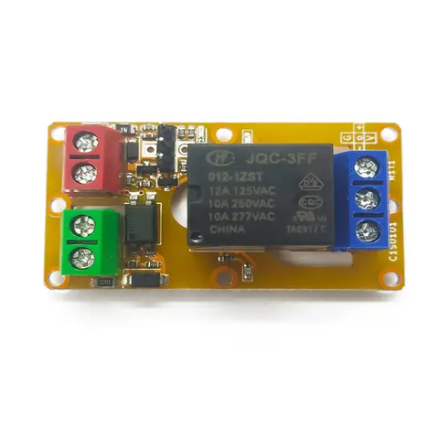
A1J0101 Economical Input Amplifier Module
Optocoupler-isolated input amplifier that turns a low-voltage signal into a 250V AC / 10A relay output.
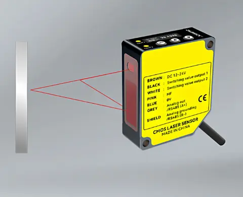
DDK-G Laser Displacement Sensor 30-250 mm
Five reference-distance grades, 20 model codes, and a choice of 4-20 mA, 0-10 V or RS485. Resolution starts at 2 um on G30 under the published test conditions; select by measuring window, target and required output.
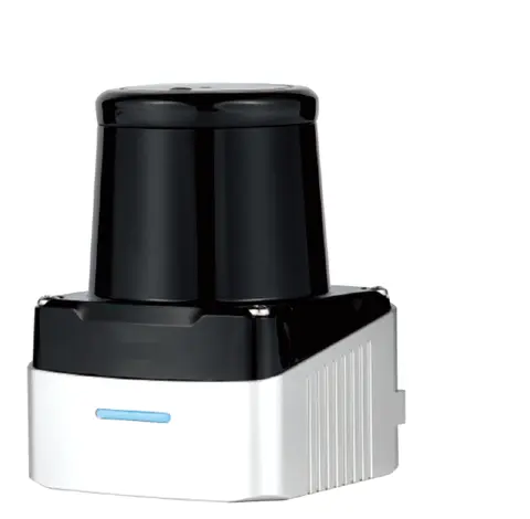
DLD-100D Single-Line TOF Scanning LiDAR
Single-line TOF scanning LiDAR with up to 100 m range, model-dependent 280°/360° coverage, and a 100 Hz / 0.32° DLD-100DP option.
Related Products in Laser Distance Sensors
DDK-F Long-range Laser Distance Sensor
Pulsed TOF laser distance sensor with up to 200 m range, stated fog/snow accuracy, IP67 and -30 to +60°C.
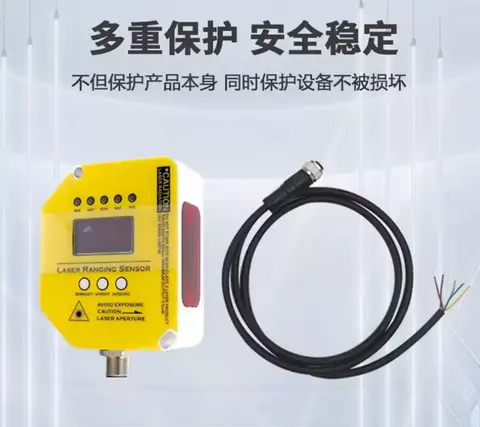
DSK-CG Long-range Laser Distance Sensor
56 models, 1 m to 80 m range, 1.5 mm-class accuracy — analog, RS-485 or dual switching outputs to match your needs.