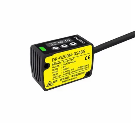
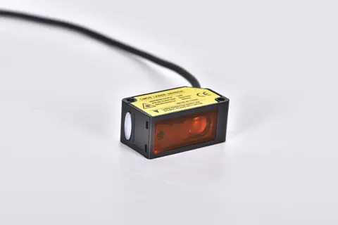
DDK-G Laser Displacement Sensor 30-250 mm
Five reference-distance grades, 20 model codes, and a choice of 4-20 mA, 0-10 V or RS485. Resolution starts at 2 um on G30 under the published test conditions; select by measuring window, target and required output.
 🔍 Click to enlarge · 1/10
ℹ The gallery preserves an earlier principle image (detail-05) whose near-limit/f.s. labels are inconsistent and whose bottom note is clipped. Do not use that image to establish dimensions or accuracy. Use the measuring-window table and updated explanatory diagram below; obtain the manufacturer's definition of F.S. before converting a percentage-linearity value into micrometres.
Technical Specifications
| Model code | DDK-G |
|---|---|
| Measurement principle | Laser triangulation onto a CMOS array: spot centroid located with sub-pixel interpolation, factory-calibrated to displacement; one raw reading per sampling cycle, averaged 1/16/64 times by response mode |
| Light source / laser class | 655 nm red semiconductor laser, max 1 mW - Class 2 (IEC/JIS), Class II (FDA) |
| Reference distances / windows | 30 mm (26-34), 50 mm (40-60), 85 mm (65-105), 120 mm (60-180), 250 mm (100-400) - all in mm |
| Resolution | High-resolution mode: 2 / 5 / 10 / 30 / 75 um by grade. Fast mode: 4 / 8 / 15 / 45 / 150 um. |
| Linearity | +/-0.1% F.S. (30/50/85/120 mm grades); +/-0.3% F.S. (250 mm grade) |
| Response time | Fast max 2 ms (1 sample) / standard max 11.5 ms (16) / high-res max 36.5 ms (64); 250 mm grade: 2.5 / 15.5 / 48.5 ms. Sampling cycle 500 us (750 us on the 250 grade). |
| Temperature drift | +/-0.08% F.S. per degC |
| Output versions | Analog current: 4-20 mA, load <=300 ohm, supply DC 12-24 V, max 60 mA. Analog voltage: 0-10 V, impedance 100 ohm, supply DC 18-24 V, max 40 mA. RS485: supply DC 12-24 V, max 40 mA. |
| Switching outputs | NPN or PNP per model, max 100 mA / DC 30 V, residual 1.8 V - two on analog versions; one on RS485 versions per the circuit diagram (factory confirmation advised) |
| MF multifunction input | Pink wire; menu-assignable to zero-set / teach / laser-off; trigger = pulse >20 ms to 0 V (NPN models) or +24 V (PNP models), then release |
| Wire colours | Brown +V, blue 0 V, black switching output 1, white switching output 2 (analog types), pink MF, grey analog output or RS485 A+, shield analog ground or RS485 B-. Blue and the shield join inside the housing - route the supply negative through blue and reserve the shield for the analog return. |
| Display / keys | OLED showing threshold Q1 and live measured value; SET + up/down keys; OUT1/OUT2 orange indicators |
| Protection | IP64; reverse-connection protection; overcurrent protection |
| Environment | Operating -10 to +45 degC (no freezing), 35-85% RH; storage -20 to +60 degC, 35-95% RH; sunlight <=10,000 lx, incandescent <=3,000 lx; vibration 10-55 Hz 1.5 mm 2 h/axis; shock approx. 50 G x3/axis |
| Warm-up | Internal circuit stable in approx. 1.5 s; rated accuracy after max 15 min warm-up |
| Construction | Aluminium alloy housing, PMMA lens; 50 (W) x 60 (H) x 20.4 (D) mm; two phi-4.5 mounting holes; 65 g cable type (excl. cable), 90 g connector type |
| Cable | phi-5, 2 m PVC, AWG24 - 6-core on analog versions, 8-core on RS485 versions; connector termination available |
| Rated test conditions | 23 degC, DC 24 V, high-resolution mode, sampling at factory setting, target at range centre, 50 x 50 mm white ceramic |
Overview
DDK-G is a CMOS laser-triangulation sensor for short-range displacement and dimensional inspection. The 30/50/85/120/250 mm figures are reference distances, not a continuous 30-250 mm measuring range. Each grade has its own measuring window, resolution, spot size and response settings; choose a window that contains the target's full movement with installation margin.
G30 offers 2 um resolution in high-resolution mode under the stated factory conditions; G250 offers 75 um with a wider 100-400 mm window. Resolution is not accuracy or repeatability. Linearity is +/-0.1% F.S. on the 30/50/85/120 grades and +/-0.3% F.S. on G250. Check the model table and test conditions before using any figure in a tolerance study.
Twenty listed codes combine five grades, NPN/PNP switching polarity and M analog or -485 communication. For M, write 4-20 mA or 0-10 V on the order because their supply ranges differ. For -485, obtain the protocol and register map before approving communication compatibility. Send the target material, actual standoff/movement, required tolerance, speed, output and quantity for a preliminary selection.
The revised English data sheet and the selection sections below bring together the model matrix, electrical versions, installation guidance and open confirmation items. This page retains its historical GDK URL; order and replacement decisions should use the complete DDK-G code, current nameplate and version-specific documentation, not the old catalogue name alone.
Start with the Measuring Window, Not the Reference-Distance Number
Measure the nearest and farthest target positions from the sensor reference plane, including part variation, fixture movement and mounting tolerance. Compare that complete interval with a grade's window. Where more than one grade fits, compare required resolution, spot size and response rather than selecting only the longest standoff.
| Grade | Reference distance | Measuring window | High-resolution mode | Linearity |
|---|---|---|---|---|
| DDK-G30 | 30 mm | 26-34 mm | 2 um | +/-0.1% F.S. |
| DDK-G50 | 50 mm | 40-60 mm | 5 um | +/-0.1% F.S. |
| DDK-G85 | 85 mm | 65-105 mm | 10 um | +/-0.1% F.S. |
| DDK-G120 | 120 mm | 60-180 mm | 30 um | +/-0.1% F.S. |
| DDK-G250 | 250 mm | 100-400 mm | 75 um | +/-0.3% F.S. |
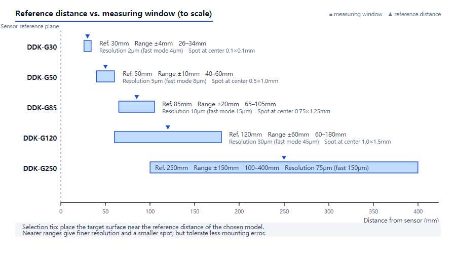
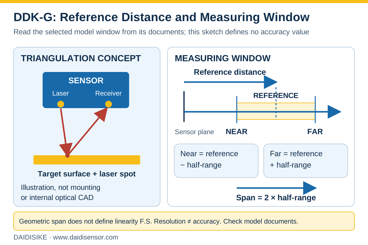
The geometric window is reference distance minus/plus the listed measuring range. Its full span is twice that plus/minus amount. This arithmetic does not settle the manufacturer's F.S. convention for linearity: obtain the written definition and conditions before converting +/-0.1% or +/-0.3% F.S. into micrometres.
Compare the other laser-displacement series if the required tolerance, environment or target is outside this model's documented capability. For metre-range positioning rather than short-stroke inspection, use the laser-distance sensor range.
Triangulation, Resolution and the Target Surface
A 655 nm laser illuminates the target and the receiving optics project reflected light onto a CMOS array. Movement along the measurement axis changes the received spot position. The published sampling cycle is 500 us on G30/G50/G85/G120 and 750 us on G250; the selected response mode averages readings and has a separate response-time limit.
The 2 um figure applies to G30 in high-resolution mode: 23 degC, DC 24 V, a 50 x 50 mm white ceramic target at range centre and the stated factory settings. Do not apply it to all grades, moving production targets or a two-head thickness system. Repeatability is not published for this series; request suitable test evidence where the acceptance tolerance depends on it.
Sample-test shiny, transparent, dark or hot targets. Target angle, surface finish, stray reflections, fixture vibration, temperature drift and response setting can change the usable result. Keep surrounding high-reflectance objects clear of the optical path and confirm the installation before committing to a production tolerance.
Choose Analog Current, Analog Voltage or RS485 Before Ordering
| Version | Measurement signal | Published supply | Integration check |
|---|---|---|---|
| M - current | 4-20 mA; load <=300 ohm | DC 12-24 V | PLC analog input, load, grounding, cable route and explicit current-output order requirement. |
| M - voltage | 0-10 V; output impedance 100 ohm | DC 18-24 V | PLC voltage input, supply floor, cable route and explicit voltage-output order requirement. |
| -485 | RS485 physical layer | DC 12-24 V | Obtain protocol/register map, communication settings and software compatibility; do not assume Modbus RTU or SPC support. |
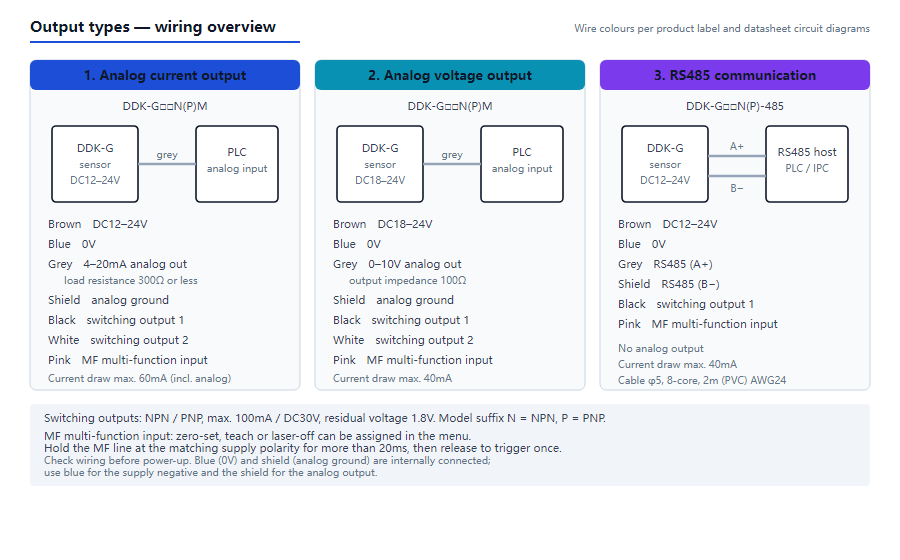
N/P selects the switching-output polarity, not the measurement interface. The analog versions publish two switching outputs; the RS485 circuit diagram shows one, with the count requiring factory confirmation where critical. For the electrical polarity decision, see the NPN/PNP compatibility guide.
Application Concepts: Height, Step and Runout Inspection
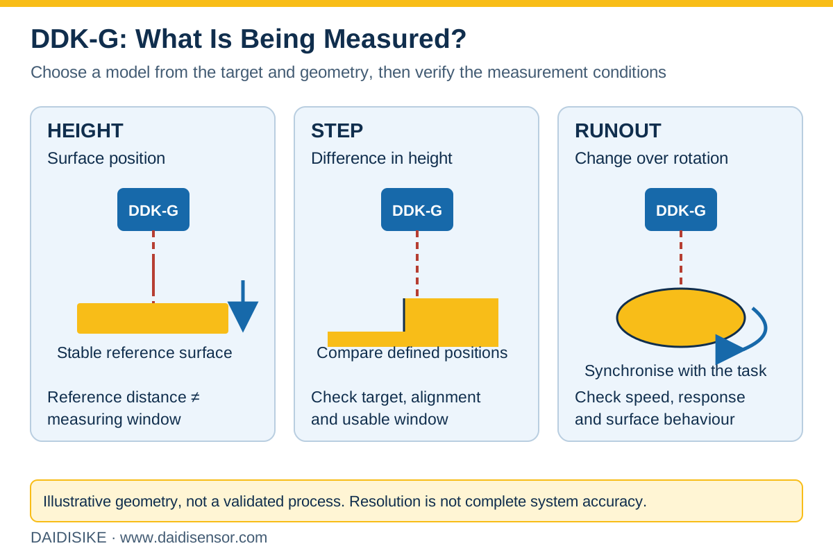
These are illustrative measurement arrangements, not verified customer installations. Height or step inspection needs a stable reference and suitable target surface. Runout measurement also depends on spindle speed, samples per revolution, averaging, mounting vibration and the acceptance method. A response-time figure alone does not approve a production speed.
For opposed-head thickness measurement, evaluate both sensors, reference-frame stability, head alignment, synchronization and the combined uncertainty. A 2 um sensor resolution does not establish 2 um system thickness accuracy, and displacement alone does not establish coating areal density.
What to Include in a DDK-G Quotation Request
- Target and geometry: material/colour/finish, target size, nearest/farthest distance, available mounting space and a sample or drawing where useful.
- Measurement requirement: tolerance and acceptance method, required repeatability evidence, target speed/takt time and the intended response mode.
- Complete code: one of the 20 listed models, N/P switching polarity, and M with '4-20 mA' or '0-10 V' explicitly stated, or -485 with the required protocol confirmation.
- Installation and supply: power voltage, dust/spray/temperature/vibration, cable or connector, required cable length and mating parts.
- Commercial set: quantity, required documents, sample evaluation and written confirmation of which cables, connectors, brackets or configuration items are included.
Use the product quotation form with the selected code and application notes. Download the revised English DDK-G data sheet for the full model and electrical tables.
Features & Benefits
Model-specific information for a purchasing decision
Compare five measuring windows, resolution/linearity by grade and three electrical versions. The English PDF provides the corresponding tables; repeatability and the RS485 protocol remain confirmation items rather than assumed capabilities.
2 um where it counts, standoff where it helps
G30 lists 2 um resolution in high-resolution mode and a 0.1 x 0.1 mm centre spot under the published conditions. G250 provides a 100-400 mm window with 75 um high-resolution-mode resolution. Select by actual movement and required measurement performance; neither figure is a system-accuracy guarantee.
Five windows to compare with the fixture
The 30/50/85/120/250 mm reference-distance options have different windows and spot sizes. Include part movement and mounting tolerance, then evaluate target behaviour near the intended operating position rather than relying on nominal distance alone.
Interface chosen at order, not adapted in the panel
Choose 4-20 mA or 0-10 V to suit the receiving analog input and installation, or RS485 after obtaining the protocol. N/P is a separate switching-output polarity choice. State the analog signal explicitly because the M suffix alone does not distinguish current from voltage.
One-touch zero after every changeover
Assign the pink MF wire to zero-set and a >20 ms pulse re-references the sensor to the new product - from the PLC, without opening the panel or touching the keys. Teach and laser-off are the other two menu options on the same wire.
Documented protection and an OLED setup display
Reverse-connection protection on the supply, overcurrent protection on the output, and both documented in the datasheet rather than assumed. The OLED panel shows threshold and live value side by side, so setup is a reading, not a guess.
65 grams, 20.4 mm thin, IP64
The aluminium housing is 50 x 60 x 20.4 mm with two phi-4.5 mounting holes; the cable-type body is 65 g excluding cable. IP64 is not a washdown or coolant-jet rating. Assess a protective enclosure or optical window with the actual environment and verify its effect on measurement.
Errata handled before they reach your incoming inspection
The factory PDF's typos - 'f.5.' for f.s., a wire-colour line contradicting the diagrams - are corrected here against the circuit diagrams and nameplate, with each verdict documented. What we could not verify (RS485 register map, repeatability) is flagged, not fabricated.
Applications
Models & Ordering Information
Analog output models (M suffix - specify 4-20 mA or 0-10 V at order)
RS485 communication models (-485 suffix)
PDF & 3D CAD Downloads
Browse all downloadsDDK-G Laser Displacement Sensor - English Datasheet
Reference revision v35: the existing model, specification and electrical tables are retained; application examples are explicitly subject to target validation. Includes the rated test conditions and site contact. Request the RS485 protocol and repeatability data separately.
Confirm the document and CAD file match the exact ordered version before installation or mechanical design. Contact us if your model is not listed.
How to Select
- Step 1 - Measure nearest/farthest target positions including movement and mounting tolerance. Choose a window that covers the full interval; the five grade numbers are reference distances, not a continuous 30-250 mm measuring range.
- Step 2 - Compare resolution, linearity and spot size at the intended position. The published resolution ratings use a white ceramic target at range centre. Test the actual target rather than treating nominal centre placement as a performance guarantee.
- Step 3 - Match the receiving interface: 4-20 mA (load <=300 ohm), 0-10 V (DC 18-24 V supply), or -485 after obtaining protocol/register documentation. Then choose N or P to match the switching-input polarity. Do not assume Modbus, SPC or multi-drop software compatibility from RS485 alone.
- Step 4 - Choose a response mode and validate the required speed. G30/G50/G85/G120 limits are 2 / 11.5 / 36.5 ms; G250 limits are 2.5 / 15.5 / 48.5 ms. Include averaging, target motion, sample count and the acceptance method.
- Step 5 - Audit the target surface before ordering: polished metal needs the head angled away from the mirror direction; transparent film echoes from both faces and demands a sample trial; very dark matte finishes call for a nearer grade; glowing-hot stock clashes with the sensor's red measurement band altogether.
- Step 6 - Wire it clean: negative rail through blue, analog return via the shield (the two join internally), the analog line kept away from power conductors, and MF on pink if you want one-touch zero-set. Allow 15 minutes of warm-up before trusting micron-level readings.
- Step 7 - Close the two open items if they matter: RS485 register map and formal repeatability data are unpublished - request both through us before committing a tolerance-critical or protocol-dependent design.
When NOT to specify the DDK-G — and what to use instead
Metre-range distance jobs: crane positioning, silo level, long-travel tracking
Why not: The longest DDK-G window ends at 400 mm from the sensor face; this is a short-range precision instrument, not a ranging device.
Use instead: a metre-range laser distance sensor such as DDA-Y/DDB-Y, DDK-F or DSK-CG
A tolerance study that must cite documented repeatability or accuracy, not resolution
Why not: The 2026 datasheet publishes resolution and linearity but no repeatability figure; acceptance criteria built on an assumed repeatability fail audits.
Use instead: requesting factory repeatability data for your target material first, or the DK-G series, which publishes repeatability figures
Washdown cells, coolant-jet zones, or condensing environments
Why not: IP64 covers dust and splash only, and the environmental table excludes freezing and condensation.
Use instead: the LK-F series with its IP67 housing, or a windowed guard / air purge in front of a DDK-G
An RS485 integration that must be designed before protocol documentation is in hand
Why not: Only the physical layer is published; the register map and protocol are factory-confirmation items.
Use instead: the 4-20 mA version into a PLC analog card, or obtaining the protocol document through us before freezing the comms design
Red-hot or self-luminous targets
Why not: Hot stock glows in the same red wavelengths the instrument measures with, corrupting the reading.
Use instead: a separate evaluation with your actual process temperatures before specifying any triangulation sensor
The five grades side by side (2026 factory datasheet)
Rated at 23 degC, DC 24 V, high-resolution mode, white ceramic target at range centre. Spot sizes defined at 1/e-squared intensity; stray light outside the spot means nearby shinier objects can disturb the reading.
| Item | DDK-G30 | DDK-G50 | DDK-G85 | DDK-G120 | DDK-G250 |
|---|---|---|---|---|---|
| Reference distance | 30 mm | 50 mm | 85 mm | 120 mm | 250 mm |
| Measuring range | +/-4 mm | +/-10 mm | +/-20 mm | +/-60 mm | +/-150 mm |
| Measuring window | 26-34 mm | 40-60 mm | 65-105 mm | 60-180 mm | 100-400 mm |
| Resolution (high-res) | 2 um | 5 um | 10 um | 30 um | 75 um |
| Resolution (fast) | 4 um | 8 um | 15 um | 45 um | 150 um |
| Linearity | +/-0.1% F.S. | +/-0.1% F.S. | +/-0.1% F.S. | +/-0.1% F.S. | +/-0.3% F.S. |
| Spot at centre | 0.1 x 0.1 mm | 0.5 x 1.0 mm | 0.75 x 1.25 mm | 1.0 x 1.5 mm | 1.75 x 3.5 mm |
| Spot near / far end | 0.15 x 0.15 both | 0.6 x 1.2 / 0.4 x 0.9 | 0.9 x 1.5 / 0.6 x 1.0 | 1.2 x 1.8 / 0.5 x 0.8 | 1.5 x 2.5 / 2.0 x 4.5 |
| Response fast / std / high-res | 2 / 11.5 / 36.5 ms | 2 / 11.5 / 36.5 ms | 2 / 11.5 / 36.5 ms | 2 / 11.5 / 36.5 ms | 2.5 / 15.5 / 48.5 ms |
| Sampling cycle | 500 us | 500 us | 500 us | 500 us | 750 us |
2026 DDK-G factory datasheet (printing errata corrected)
Specifications we do not publish yet
We only publish a figure once we are confident it is true. The items below are still being validated through further testing and real-world customer feedback, so for now we would rather leave them open than guess. If one of them matters to your design, ask us for the latest validated status.
- The source does not resolve the F.S. convention consistently between its specification and principle labels. Request the manufacturer's written definition and test conditions before converting percentage linearity or temperature drift to micrometres.
- Repeatability is not published for this series - request factory test data for tolerance-critical duties.
- The RS485 protocol / register map is not published; only the physical layer (RS485, A+/B-) is documented.
- Whether the two switching outputs on analog versions support independent thresholds is not stated in the datasheet.
- The -485 variant's switch-channel count reads as one on the circuit drawing yet merges ambiguously in the spec table - treated as single here pending factory clarification.
- Footnote markers *2 and *3 in the factory datasheet have no corresponding note text; no content has been invented for them.
Frequently Asked Questions
Why did the model name change from GDK to DDK-G?
Which grade should I order if my mounting distance is, say, 70 mm?
What resolution do I actually get, and under what conditions?
Is resolution the same thing as accuracy for tolerance studies?
What is the difference between the M and -485 versions in daily use?
What does the pink wire do?
What changed in the revised English data sheet, and how are source inconsistencies handled?
Can it measure shiny, transparent or black targets?
Is IP64 enough for my environment?
Does the RS485 version speak Modbus RTU?
Can the DDK-G act as a safety sensor for personnel protection?
What should be on the purchase order so nothing bounces?
Related Categories and Example Products
Explore other functions that may be needed in a machine or line. The products below are category examples, not pre-validated electrical or safety combinations. Confirm each interface and application separately: Laser Distance Sensors · Contact Displacement Sensors · Relay & Timer Modules
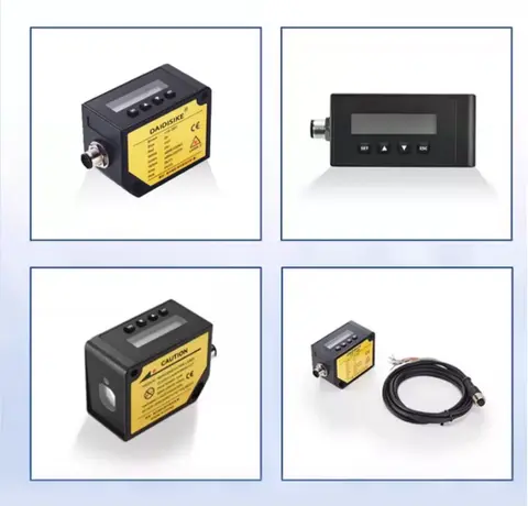
DDA-Y & DDB-Y Industrial Laser Distance Sensor (Phase-Shift)
Phase-shift laser distance sensors: 0.2-100 m range, millimeter accuracy, RS485 Modbus RTU, switching or analog output.
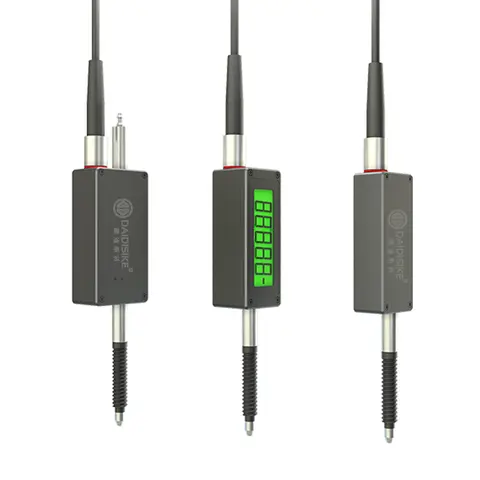
JNS-Q Contact Displacement Grating Sensor
Digital, RS-485-networkable contact displacement sensor with resolution down to 0.2 micron for inline dimensional inspection.
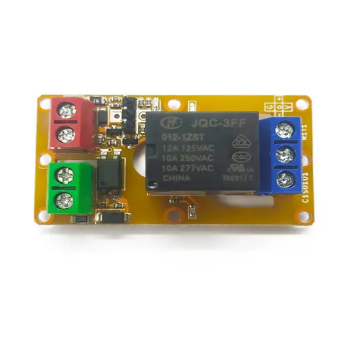
A1J0101 Economical Input Amplifier Module
Optocoupler-isolated input amplifier that turns a low-voltage signal into a 250V AC / 10A relay output.