
B2J0401 MODBUS Analog/Digital I/O Module
Economical MODBUS-RTU/RS-485 module: 4 analog/digital inputs plus 2 MOSFET PWM/PTO outputs.
 🔍 Click to enlarge · 1/6
Technical Specifications
| Physical Interface | RS-485 half-duplex, differential twisted pair A/B |
|---|---|
| Communication Protocol | MODBUS-RTU (RS-485 physical layer) |
| Configuration / Upgrade Interface | Onboard USB port (connect within 10s of power-up to enter configuration mode; not connected during normal use) |
| Inputs | 4 x digital/analog dual-use inputs DIN0-3 / AIN0-3 (same terminal, with pulse counting and debounce filtering) |
| Outputs | 2 x open-drain MOSFET outputs DOUT0/DOUT1 (digital output or PWM/PTO pulse output) |
| PWM Support | Standard PWM, standard PTO, fast PWM (PTO on channels 0/1 only; fast PWM on channel 0 only) |
| Default Baud Rate | 9600 bps |
| Default Data Format | 8 data bits, even parity, 1 stop bit |
| Default Slave Address | 0x02 |
| Selectable Baud Rates | 4800 / 7200 / 9600 / 14400 / 19200 / 28800 / 38400 / 57600 / 76800 / 115200 bps |
| Selectable Parity | None / Odd / Even (default Even) |
| Selectable Stop Bits | 1 (default) / 1.5 / 2 |
| Slave Address Range | 1-247 (0x01-0xF7) |
| Digital Input Threshold | Approx. 3V (above = high level, below = low level) |
| Input Pulse Counting | +1 per rising edge per channel, rollover at 65535; frequency <=5Hz |
| Input Filtering | Configurable 1-65535ms per channel (1ms per unit) |
| Analog Input | 16-bit register, LSB = 1mV; effective resolution 8-bit, typical full-scale accuracy 3% |
| Supply Voltage (9V DC version) | 8.5-11V |
| Supply Voltage (12V DC version) | 11-14V |
| Supply Voltage (24V DC version) | 20-28V |
| Supply Ripple | <1Vp-p |
| Supply Current | <50mA (typical 20mA) |
| Output Stress, Standard MOSFET Type | DC 40V, 1000mA |
| Output Stress, High-Current MOSFET Type | DC 20V, 2000mA |
| Output Stress, High-Voltage MOSFET Type | DC 100V, 100mA |
| All Input Terminals (operating) | DC 0-30V |
| RS-485 Port (operating) | Peak <5V |
| Operating Temperature | -20 to 60 deg C |
| Max Supply Voltage (9V/12V/24V versions) | DC 11.5 / 15 / 30V |
| Resettable Fuse | DC 60V, 100mA |
| Max Output Stress, Standard MOSFET Type | DC 60V, 1500mA |
| Max Output Stress, High-Current MOSFET Type | DC 30V, 3000mA |
| Max Output Stress, High-Voltage MOSFET Type | DC 150V, 200mA |
| All Input Terminals (absolute max) | DC 50V |
| RS-485 Port (absolute max) | Peak <50V |
| Storage Temperature | -40 to 85 deg C |
| ESD Immunity (IEC61000-4-2) | 4kV to all input and power terminals, normal operation (criteria A) |
| EFT Immunity (IEC61000-4-4) | 2kV/5kHz/2min, normal operation (criteria A); 4kV/5kHz/2min, no permanent damage (criteria C) |
| EMC Test Condition | 12V supply, well grounded, unit operating; supply negative must be directly grounded to achieve above ratings |
| PCB Dimensions | 55mm x 30mm (tolerance +/-5%) |
| Mounting Hole Spacing | 49mm (vertical) x 24.5mm (horizontal) |
| Terminal Pitch | 5.08mm |
| Terminals & Indicators | 14 screw/pin terminals + 1 USB port + 4 LED indicators (communication-red, power-green, output0-blue, output1-blue) |
Overview
The B2J0401 is an economical MODBUS-RTU / RS-485 analog input and pulse output module built around a dedicated integrated circuit (ASIC). It is designed for engineers who need a low-cost RS-485 slave device that combines analog/digital sensing with motor, stepper and heating output control on low-voltage DC circuits, and is supplied in 5V, 9V, 12V, 18V and 24V DC versions (custom voltages available).
It provides 4 digital/analog dual-use inputs (DIN0-3 / AIN0-3) with built-in pulse counting and 1-65535ms input filtering, plus 2 open-drain MOSFET outputs (DOUT0/DOUT1) supporting direct drive, on-delay with 5 trigger modes, standard PWM, standard PTO and fast PWM. Its process-brake logic is not a personnel-safety function. Communication parameters and firmware can be configured through USB. Inputs and outputs are non-isolated: normal inputs are listed at DC 0-30V, while output ratings depend on the selected MOSFET variant. The 50V input absolute maximum is not an operating rating for the whole module. Do not switch AC mains with this module.
Features & Benefits
One Terminal Does Two Jobs on All 4 Inputs
Every one of the 4 input terminals reads either a 16-bit analog value (LSB = 1 mV, DC 0-30 V range, typical 3% full-scale accuracy) or a digital contact (threshold about 3 V) - the same terminal, no jumper and no separate AI and DI cards. When a channel changes role from a level sensor to a limit switch, you rewrite a register instead of re-wiring the panel.
Per-Channel Debounce Filter Kills Contact Chatter
Each input has its own filter settable from 1 to 65535 ms in 1 ms steps, so a bouncing relay contact or a float switch stops producing phantom transitions. Every channel also counts rising edges up to 65535 (rollover to zero) at up to 5 Hz, so a flow meter or product counter is read straight from a register - no high-speed counter card and no counting loop in the master.
Motion and Power Control Without a Motion Controller
The 2 open-drain MOSFET outputs do far more than switch on and off: direct drive, on-delay with 5 trigger modes, standard PWM, standard PTO (channels 0 and 1) and fast PWM (channel 0). One 55 x 30 mm board sends PUL on channel 0 and DIR on channel 1 to a stepper driver, or holds a heater at temperature with fast PWM - work that normally needs a separate pulse-output module.
A Brake the Master Cannot Talk Its Way Past
BRKCFG sets which input is the brake and whether it trips high or low, plus its sensitivity. Once tripped, the outputs are blocked immediately and BRKFLG latches to "BK" until it is cleared remotely over the communication port - and brake outranks any forced output. A crashed master, a bus glitch or a stuck coil command cannot restart a braked motor.
Settings That a Noisy Bus Cannot Rewrite
Sensitive registers such as NAME, SRLCFG and BRKCFG only accept a write after ASCII "UL" (0x554C) is written to SAFELCK, and the module re-locks itself after every single write, on any CRC error, and even on traffic addressed to other slaves. Confirmed settings are stored permanently by writing ASCII "MS" (0x4D53) to MODESAVE. If a node is ever lost, the onboard USB port - connected within 10 s of power-up - restores 9600 bps / 8 data bits / even parity / 1 stop bit / address 0x02 and loads new firmware, so a mis-set baud rate is a two-minute fix, not a return.
11 Modbus Function Codes, Not the Usual Four
Beyond 0x01-0x06 the module answers 0x0F write multiple coils, 0x10 write multiple registers, 0x16 mask write, 0x17 read/write multiple registers and 0x11 report device ID (product ID 0x2404), and it returns four distinct exception codes (ENOFUNC, ENOADR, EINVAL, EDEVICE) so a failed write tells you why. It drops onto any MODBUS-RTU master at 4800-115200 bps with addresses 1-247, and one 0x17 transaction can read all inputs and update both outputs.
EFT Immunity at Twice the Industrial Requirement
Tested to IEC61000-6-2-2016, the power and input terminals withstand 4 kV ESD (IEC61000-4-2) and 2 kV/5 kHz EFT (IEC61000-4-4) with normal operation - double the 1 kV the general industrial standard asks for - and survive 4 kV EFT without permanent damage. Reverse-supply, overcurrent and inductive-load flyback protection are built in, and an input-reinforced "XS" variant is available where drives and contactors make the cabinet harsher still. Certification documents are available on request.
Match the Load Without Redrawing the Harness
Order the output stage as standard (DC 40 V / 1000 mA), high-current (DC 20 V / 2000 mA) or high-voltage (DC 100 V / 100 mA) MOSFET - the wiring is identical across all three - and the supply as 5, 9, 12, 18 or 24 V DC (custom on request). The board draws a typical 20 mA, fits 55 x 30 mm with 5.08 mm terminal pitch, runs -20 to 60 deg C, and for volume orders the communication parameters can be fixed and unused terminals, buttons or LEDs deleted to cut cost.
Applications
Models & Ordering Information
B2J0401 Series
How to Select
- Bare-board supply, enclosure and DIN-rail mounting are ordering options for this B2J/E4J module. Specify what is included on the quotation; do not assume an enclosure or mounting kit is supplied as standard.
- Choose the B2J0401 when the application needs analog/digital sensing combined with multi-mode PWM/PTO transistor output and a configurable process-brake input (not a personnel-safety function), such as motor speed control, stepper motion, heating power control or analog monitoring.
- Inputs and outputs are non-isolated. Keep input signals within the listed DC 0-30V operating range, and select output voltage/current limits from the exact MOSFET variant's normal ratings. Do not use the 50V absolute-maximum input figure as an operating voltage or a universal output limit. Do not switch AC mains.
- For a single load that may be mains-voltage, choose the relay-isolated single-channel B2J0302 (up to 250V AC / 10A) instead.
- Select the MOSFET output variant by load current and voltage: standard, high-current or high-voltage as required. Confirm the complete voltage/output suffix and its wiring diagram on the quotation; do not infer the suffix from another model.
- All digital outputs may briefly turn on for about 50ms during power-up/power-down (especially transistor types); for timing-sensitive loads, add power sequencing or consider a relay-output model instead.
📘 Need the full method? NPN vs PNP Sensor Outputs Explained
When NOT to specify the B2J0401 — and what to use instead
A load must be switched by a volt-free (relay) contact rather than a solid-state output
Why not: Both B2J0401 outputs (DOUT0/DOUT1) are open-drain MOSFET types only, supporting direct drive, on-delay, PWM and PTO - there is no relay/contact output variant of this board.
Use instead: B2J0302 (single-channel relay-isolated, up to 250V AC / 10A) or the D3J0202/D3J0204/D3J0208/D3J0214 relay-output family
The circuit to be switched carries mains (AC) voltage
Why not: B2J0401 has non-isolated DC inputs and MOSFET outputs and must not switch AC mains. Inputs are listed at DC 0-30V in normal operation. Output ratings vary by selected MOSFET type; the 50V input absolute maximum and higher output absolute maxima are not normal operating ratings.
Use instead: B2J0302 (relay-isolated, up to 250V AC / 10A)
More than 2 output channels are needed
Why not: The B2J0401 board provides exactly 2 open-drain MOSFET outputs (DOUT0/DOUT1); there is no higher-channel-count version of this specific module.
Use instead: D3J0204, D3J0208 or D3J0214 for output-only expansion; check the exact output type, current and supply. D3J01 models are input modules, not output expansion.
The application needs a machine safety stop function (e-stop, guard interlock, safety light curtain OSSD)
Why not: The B2J0401 carries no safety rating (no Type/SIL/PL) and its emergency-brake function is a configurable digital-logic feature, not a certified safety function; its outputs are not OSSDs.
Use instead: DA31 Emergency-Stop Safety Relay Module or DQSRN Safety Relay Module - never use the B2J0401 in a machine safety function
The panel needs finer analog accuracy than the module's typical 3% full-scale reading
Why not: Each B2J0401 analog input is a 16-bit register (LSB = 1mV) but effective resolution is only 8-bit with a typical 3% full-scale accuracy - it is a general sensing input, not a precision acquisition channel.
Use instead: consult DAIDISIKE for a dedicated precision analog acquisition device; no sibling in this delay/relay-module range offers tighter analog accuracy
Standalone field configuration without any RS-485 master or PC is required
Why not: Every B2J0401 parameter (baud rate, address, brake, output mode) is set through RS-485 registers or the USB configuration software; the board has only 4 LED indicators and no digit display or keys for on-site setup.
Use instead: E4J0101 / E4J0102 / E4J0103 (on-board digit-tube display and keys for standalone field setup)
Specifications we do not publish yet
We only publish a figure once we are confident it is true. The items below are still being validated through further testing and real-world customer feedback, so for now we would rather leave them open than guess. If one of them matters to your design, ask us for the latest validated status.
- MOSFET output switching life / duty-cycle rating under rated load
- MTBF (mean time between failures)
- IP / ingress-protection rating of the bare PCB or optional enclosure
- Terminal wire gauge and screw-torque specification for the 5.08mm terminals
- Formal EMC/safety certification status and certificate number (only ESD/EFT test results are published)
- USB cable type, connector and maximum cable length for configuration
Frequently Asked Questions
What is the B2J0401 relay module used for?
Can the B2J0401 switch mains (AC) voltage loads?
How do I configure the B2J0401's communication parameters?
What output functions does each channel support?
How does the emergency brake function work?
What power supply voltages are available?
Can communication parameters be fixed or hardware simplified for OEM production?
Is the B2J0401 certified for industrial EMC compliance?
Related Categories and Example Products
Explore other functions that may be needed in a machine or line. The products below are category examples, not pre-validated electrical or safety combinations. Confirm each interface and application separately: Proximity Sensors · Photoelectric Sensors · Laser Distance Sensors

D6.5 Series Inductive Proximity Sensors (Ultra-Short 18mm / Y-Type / 35mm / 45mm)
6.5mm-diameter inductive proximity sensors for tight-clearance mounting where M8 sensors won't fit.
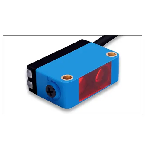
BGS-CX441 / BGS-CX442 Background Suppression Photoelectric Sensor
Wire-adjustable BGS sensor with 2 mm or 15 mm spot, 10-300 mm range, published black/white differential distance.
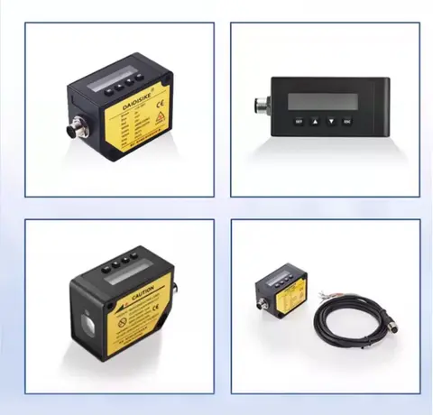
DDA-Y & DDB-Y Industrial Laser Distance Sensor (Phase-Shift)
Phase-shift laser distance sensors: 0.2-100 m range, millimeter accuracy, RS485 Modbus RTU, switching or analog output.
Related Products in Relay & Timer Modules
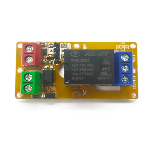
A1J0101 Economical Input Amplifier Module
Optocoupler-isolated input amplifier that turns a low-voltage signal into a 250V AC / 10A relay output.
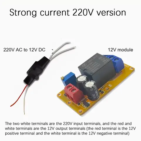
B2J0101 Economical Power-up Delay Module
Low-cost power-up delay relay module with a 2-30 second adjustable delay and no trigger input required.
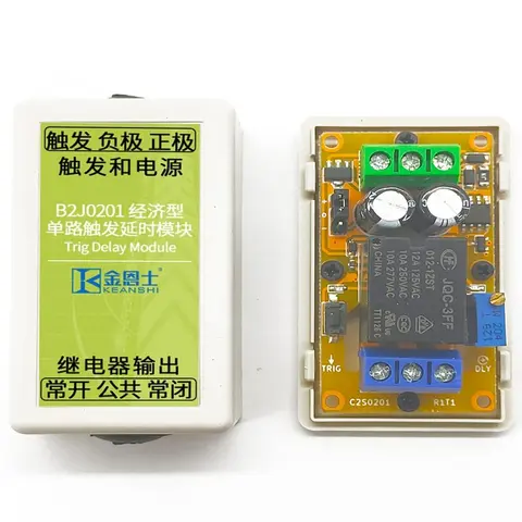
B2J0201 Economical Trigger Delay Module
Level-triggered delay relay module with jumper-selectable high/low trigger and a 2-30s adjustable delay.
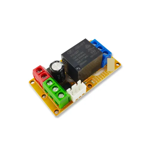
B2J0302 Enhanced Single MODBUS-485 I/O Module
Enhanced single-channel MODBUS-RTU/RS-485 I/O module: 1 digital input, 2 analog inputs, 1 relay or transistor output, AT command support and a 5V sensor supply — the successor to the discontinued B2J0301.