
E4J0102 Easy Multifunctional Clock-Trigger Delay Module
Analog voltage-threshold triggering plus an optional real-time clock, in one multi-function delay relay module.
 🔍 Click to enlarge · 1/7
Technical Specifications
| Type / delay modes | Single-channel digital delay relay module with analog voltage-threshold trigger; about 100 base templates x polarity inversion = about 1,000 delay modes across 5 groups (switching, delay-off, delay on/off, cyclic, counting) |
|---|---|
| Analog trigger input | One non-isolated differential analog voltage input (terminals 2/3), non-polarized; each terminal 0-30V to supply negative; trigger voltage = absolute value of the difference between the two terminals |
| Threshold resolution / accuracy | 0.01V threshold-setting resolution (0-39.99V range); analog-to-digital conversion accuracy about 0.1V (AT+ADC? returns voltage in 1mV steps) |
| Detection modes | Hysteresis mode when high threshold >= low threshold (Schmitt-trigger style, anti-chatter); range mode when high threshold < low threshold (in-range = high level, for voltage-window/clamp alarms) |
| On-board voltmeter | Press and hold the S key in standby to display the current trigger voltage on the 4-digit display, in 0.01V units |
| Delay times A / C | 0-999 x time unit each (10ms / 100ms / 1s / 10s / 1min / 10min / 1h / 10h); a value of 0 is treated as 10ms |
| Cycle count L | 0-9999; 0 means infinite (cyclic group) or unlimited / not triggered (counting group) |
| Delay accuracy | About 1% factory typical (2% worst case); calibratable via PC software to within 0.05% (calibration value 0-100, default 50, about 0.05% per step, +/-2% range) |
| Real-time clock (selected versions) | Battery-backed RTC (keeps time through power loss) with optional buzzer alert; up to 8 calendar trigger points (H--0 to H--7, count set by A--F: 0/1/4/8); each clock trigger produces about a 500ms trigger pulse |
| RTC calendar settings | Year (20XX), month (01-12), day (01-31, leap-year checked), hour (00-23), minute (00-59), second (00-59); wildcards supported: '--' = ignore, month -1~-4 = quarters, day -1~-7 = Monday-Sunday, -8 = weekday, -9 = weekend, hour -1/-2 = AM/PM |
| RTC accuracy (calibrated, continuous power) | Instantaneous daily drift 10s/day typ, 20s/day max; real-world daily drift 0.5s/day typ (15s/month), 2s/day max (1min/month); calibration-point indication difference 0.5s typ, 1s max; full-day max indication difference 5s typ, 10s max; temperature coefficient 0.1s/day/C typ, 0.2s/day/C max |
| Configuration | 4-digit display + 4 keys (M/S/+/-) for on-site setup, or USB connection to a computer with configuration software |
| USB interface / AT commands | USB virtual serial port with an AT command set (no echo); AT -> OK; AT+TRG simulates a ~500ms trigger; AT+ADC? reads the analog input voltage in 1mV steps; AT+PIN? reads the post-threshold digital level (0/1); AT+OUT= / AT+OUT? writes/reads the output (write only takes effect in mode 0200) |
| Firmware options | Standard firmware (all functions adjustable); quick-adjust firmware (polarity, delay mode and clock locked, only delay times A/C and cycle count L quickly adjustable); custom firmware (1xxxx numbering, fixed non-standard delay timing, consult factory) |
| Output | Arc-suppression relay or transistor, selected by ordering code |
| Output stress (normal operating) | Relay type: DC 30V or AC 0-220V, 8A; Transistor type: DC 12-48V, 8A |
| Output isolation voltage (normal operating) | Relay type: < 250V; Transistor type: < 130V |
| Trigger input stress (normal operating) | DC 0-30V |
| Supply voltage (rated) | 5V / 9V / 12V / 24V DC |
| Supply voltage (normal operating range) | 5V DC: 4.8-5.2V; 9V DC: 8.5-11V; 12V DC: 11-14V; 24V DC: 20-28V |
| Power supply ripple | < 1Vp-p |
| Supply current | < 200mA (typically 40mA when the relay is made) |
| Operating temperature | -20 to 60 degrees C |
| Absolute max supply voltage | 5V: 5.3V; 9V: 11.5V; 12V: 15V; 24V: 30V DC |
| Self-resettable fuse | DC 60V, 500mA |
| Absolute max output stress | Relay type: AC 250V, 10A; Transistor type: DC 55V, 10A |
| Absolute max trigger input | DC 50V |
| Absolute max input isolation voltage | DC 1000V, 60s (type test only) |
| Absolute max output isolation voltage | Relay type: DC 1000V, 60s (type test only); Transistor type: DC 250V, 60s (type test only) |
| Storage temperature | -40 to 85 degrees C |
| Relay mechanical life | > 100,000 operations (> 10,000 under heavy load) |
| Electrostatic discharge resistance | EN61000-4-2: 4kV on all terminals, module functions normally |
| Electrical fast transient resistance | EN61000-4-4: 2kV/5kHz/2min on all terminals, module functions normally; 4kV/5kHz/2min, module not permanently damaged |
| Surge resistance | EN61000-4-5: 1kV to ground on all terminals, module not permanently damaged |
| Creepage distance | > 6.05mm from relay terminal (primary side) to logic side, pollution degree 3, material category IIIa/IIIb, basic insulation (requirement > 6mm) |
| Electrical clearance | > 2.1mm from input and relay terminals to logic side, pollution degree 3, basic insulation (requirement > 2mm) |
| Dimensions | 66mm (L) x 41mm (W) x 20mm (H), tolerance +/-5% |
| Terminal spacing | 5.08mm |
| Terminals and interfaces | 7 screw terminals + 4 keys (M/S/+/-) + 1 four-digit display + 3 LEDs + 1 USB port + 1 optional buzzer |
Overview
The E4J0102 is a multi-functional single-channel digital delay relay module built around a dedicated ASIC, for control circuits that need to trigger a relay or transistor output from an analog voltage level or from a calendar time point, rather than from a simple digital switch signal. It runs from 5V, 9V, 12V or 24V DC, replaces the digital trigger input used on the E4J0101 with one non-isolated differential analog voltage input (0-30V), and switches one arc-suppression relay or transistor output.
On-board configuration uses a 4-digit display and 4 keys, plus a USB port for PC-based setup, input/output read-back and firmware upgrades. About 100 base delay templates combine with input/output polarity inversion into roughly 1,000 delay modes across five groups (switching, delay-off, delay on/off, cyclic and counting delay), with delay times A and C each adjustable from 0-999 in 8 selectable time-unit steps (10ms to 10h) and a cycle count of 0-9999. Selected versions add a battery-backed real-time clock with up to 8 calendar trigger points and an optional buzzer.
Features & Benefits
Triggers On A Voltage Level, So The Signal Conditioner Disappears
One non-isolated differential analog input (terminals 2/3, 0-30V per terminal) measures a voltage directly and fires the output on a threshold set in 0.01V steps anywhere from 0 to 39.99V. That removes the comparator board, threshold relay or transmitter a digital-input timer needs in front of it: a sensor, battery or supply rail wires straight to the module. Hold the S key in standby and the 4-digit display becomes a live voltmeter in 0.01V units, so the threshold is dialed in against the real signal at the terminal instead of being guessed from a datasheet.
Non-Polarized Differential Input Removes A Whole Class Of Wiring Faults
The two detection terminals have no polarity: the trigger value is the absolute difference between them, so either lead can go to either terminal and the reading is still correct. Each terminal only has to sit within 0-30V of the supply negative, and the absolute maximum on the trigger input is DC 50V. In a panel that means one less mistake an installer can make, and one less service call when a sensor is swapped in the field.
Hysteresis Or Window Detection From The Same Two Terminals
Set the high threshold at or above the low threshold and the input behaves as a Schmitt trigger: it goes high above U--H and only returns low below U--L, so a noisy signal drifting between the thresholds cannot chatter the relay, which is exactly what a heater or level loop needs. Set the high threshold below the low threshold and the same input flips to range mode, where only an in-window voltage counts as high, giving an over/under-voltage window alarm. Two control laws from one part number, changed with a menu value rather than a hardware change.
Battery-Backed Clock Turns Calendar Rules Into Hardware You Don't Have To Buy
RTC versions (ordering-code digit 3 = 2 or 3) carry an on-board battery that keeps time through power loss, plus up to 8 trigger points each producing about a 500ms trigger pulse into the delay engine. The wildcard system is what makes it useful: '--' ignores a field, month accepts -1 to -4 for quarters, day accepts -1 to -7 for Monday through Sunday plus -8 for weekdays and -9 for weekends, and hour accepts -1/-2 for AM/PM. So 'every statutory workday at 09:00', 'every Friday on the hour' or 'every year on 29 May' becomes one trigger point instead of a time switch plus a timer plus a contactor.
About 1,000 Delay Modes Means One Stock Item Covers The Whole Panel
Roughly 100 independent base templates across five groups (switching, delay-then-break, delay-make-then-break, cyclic and counting) each derive four sub-modes from input and output polarity inversion, for about 1,000 usable delay modes. Delay times A and C are each 0-999 multiplied by a unit of 10ms, 100ms, 1s, 10s, 1min, 10min, 1h or 10h, and the cycle count L runs 0-9999 with 0 meaning infinite. Pulse, off-delay, on-delay, repeat-cycle and counting jobs from 10 milliseconds upward all come out of the same drawer.
Configure At The Panel Or From A PC, Not One Or The Other
The 4-digit display and M/S/+/- keys set every parameter on site with no software, no cable and no laptop: long-press M to unlock, +/- to pick a menu, S to select the digit, long-press M to save and exit. When automation is wanted instead, the USB port enumerates as a virtual serial port with an AT command set - AT+ADC? reads the analog input in 1mV steps, AT+PIN? reads the post-threshold level, AT+TRG fires a ~500ms test trigger, AT+OUT= / AT+OUT? write and read the output - which makes commissioning and end-of-line test scriptable. Firmware upgrades over the same port add functions without swapping hardware.
Calibration Reaches 0.05% Timing And About 1 Second A Day Of Clock Drift
Out of the box the delay is accurate to about 1% (2% worst case), which is enough for most timing. When it isn't, the PC software's clock-calibration field (0-100, default 50, about 0.05% per step over a +/-2% span) trims it to within 0.05%, with calibration against a 1000-second delay the recommended method. On RTC versions the built-in calibration routine settles in about 5 days and then holds real-world drift near 1 second per day, which is what stops a year-long calendar schedule creeping out of its time slot.
Industrial EMC And Safety Headroom Built Into The Board
This is a genuine industrial part rather than a hobby timer: 2000V EFT at 5kHz for 2 minutes and 4kV ESD on all terminals with normal operation, and no permanent damage at 4kV EFT or at 1kV surge to ground - twice the 1kV EFT that the IEC 61000-6-2 industrial baseline asks for. The power input carries reverse-polarity, overcurrent and surge protection plus a DC 60V / 500mA self-resetting fuse, and the PCB is slotted on the high-voltage side to measure over 6.05mm creepage and over 2.1mm clearance to the logic side, against 6mm and 2mm requirements at pollution degree 3. Certification documents are available on request.
One Ordering Code Sets Supply, Output And Clock, Including A Hardened Input
E4J0102R[a]T[b]M[ccc] selects supply (1=5V, 2=9V, 3=12V, 4=24V), output (1=relay, 2=transistor) and clock (1=none, 2=RTC, 3=RTC with buzzer) independently, so a job is specified exactly rather than paying for a stack of unused options: M311 for plain voltage-threshold control, or the default M313 (12V, relay, RTC with buzzer) when everything is wanted. The relay type switches DC 30V or AC 0-220V at 8A for over 100,000 operations; the transistor type drives 12-48V DC inductive loads silently through an on-board 10A flyback diode. Where EFT pulse trains land on the analog input frequently, the 'XS' suffix adds input-resistor hardening instead of leaving a filter to be built on site.
Applications
Models & Ordering Information
E4J0102 Ordering Code
How to Select
- Bare-board supply, enclosure and DIN-rail mounting are ordering options for this B2J/E4J module. Specify what is included on the quotation; do not assume an enclosure or mounting kit is supplied as standard.
- Choose the E4J0102 when the trigger needs to come from an analog voltage level (0-30V) rather than a digital on/off signal, or when the action must fire at a specific calendar date and time.
- Use hysteresis mode (high threshold >= low threshold) for anti-chatter control such as temperature or level regulation; use range mode (high threshold < low threshold) for voltage-window or over/under-voltage alarms.
- Order an RTC-equipped configuration (ordering-code digit 3 = 2 or 3) only when calendar-based triggering is required; the base configuration (digit 3 = 1, no RTC, no buzzer) is enough for pure voltage-threshold applications such as sauna temperature control.
- Add the buzzer option (digit 3 = 3) when an audible alert at each clock trigger is useful, for example unattended reminders.
- If the trigger signal is a simple digital on/off level (button, sensor output or remote control) rather than an analog voltage, choose the E4J0101 instead.
- If two relay outputs need to run independently or in coordination, such as motor forward/reverse, with RS-485 MODBUS, choose the E4J0103 instead.
- For installations with frequent EFT pulse trains directly on the analog input, order the input-resistor-reinforced version with the 'XS' suffix, since the standard analog-input EFT rating applies to sparse pulse bursts.
- Choose the transistor output version for frequent-triggering or silent-switching 12-48V DC inductive loads, and add power sequencing (module powered up first, then output; output powered down first, then module) since the transistor output can briefly conduct at power-on/off.
📘 Need the full method? NPN vs PNP Sensor Outputs Explained
When NOT to specify the E4J0102 — and what to use instead
The trigger source is a simple digital on/off signal (button, sensor contact, remote) rather than a voltage level or calendar time
Why not: The E4J0102's trigger input is a non-isolated differential analog voltage input (0-30V per terminal, threshold set in 0.01V steps); it has no digital optocoupler trigger input like the E4J0101.
Use instead: E4J0101 (digital trigger input, with optional wireless remote)
No calendar/schedule triggering is needed at all - only a fixed elapsed-time delay from a voltage level
Why not: The RTC-equipped configuration (ordering digit 3 = 2 or 3) adds a battery-backed clock and up to 8 calendar trigger points that go unused if only voltage-threshold delay is required.
Use instead: the E4J0102 base configuration (digit 3 = 1, no RTC) for pure voltage-threshold use
Two independent or linked output channels are needed (for example forward/reverse or sequential start)
Why not: The E4J0102 is single-channel with one relay or transistor output; it has no second output and no channel-linkage modes.
Use instead: E4J0103 (dual-channel with four linkage modes and optional RS-485/MODBUS)
The clock schedule must hold near-zero drift over long unattended periods without recalibration
Why not: The E4J0102 RTC drifts a typical 0.5s/day (2s/day worst case) even after calibration, and the calibration routine itself takes about 5 days to settle; uncalibrated instantaneous drift can reach 20s/day.
Use instead: E4J0103 (RTC option typically drifts 0.25s/day) for a tighter long-term schedule
The application needs a machine safety stop function (e-stop, guard interlock)
Why not: The E4J0102 carries no safety rating (no Type/SIL/PL); it is a general-purpose delay relay, not a safety component, and its output is not an OSSD.
Use instead: DA31 Emergency-Stop Safety Relay Module or DQSRN Safety Relay Module - never use the E4J0102 in a machine safety function
The installation has dense or frequent EFT pulse trains landing directly on the analog trigger input
Why not: The standard analog-input EFT rating (2kV/5kHz) is validated for general terminal conditions; the module's own datasheet flags that frequent EFT bursts specifically on the analog input call for the input-resistor-reinforced version.
Use instead: order the E4J0102 with the 'XS' suffix instead of the standard variant
Specifications we do not publish yet
We only publish a figure once we are confident it is true. The items below are still being validated through further testing and real-world customer feedback, so for now we would rather leave them open than guess. If one of them matters to your design, ask us for the latest validated status.
- RTC backup battery type, capacity and expected replacement interval
- MTBF (mean time between failures)
- IP / ingress-protection rating
- Terminal wire gauge and screw-torque specification for the 5.08mm terminals
- Formal 3C/CE certification status and certificate number — certificate pending; documents available on request once issued
- USB cable type, connector and maximum cable length for configuration
Frequently Asked Questions
What is the E4J0102 clock-trigger delay module used for?
How does the analog voltage trigger work in hysteresis vs range mode?
Does the E4J0102 have a real-time clock for time-of-day triggering, and how accurate is it?
How do I configure the E4J0102 — on-board keys or USB software?
What is the difference between the E4J0102 and the E4J0101?
Does the E4J0102 carry industrial safety or compliance certification?
Related Categories and Example Products
Explore other functions that may be needed in a machine or line. The products below are category examples, not pre-validated electrical or safety combinations. Confirm each interface and application separately: Proximity Sensors · Photoelectric Sensors · Laser Distance Sensors

D6.5 Series Inductive Proximity Sensors (Ultra-Short 18mm / Y-Type / 35mm / 45mm)
6.5mm-diameter inductive proximity sensors for tight-clearance mounting where M8 sensors won't fit.
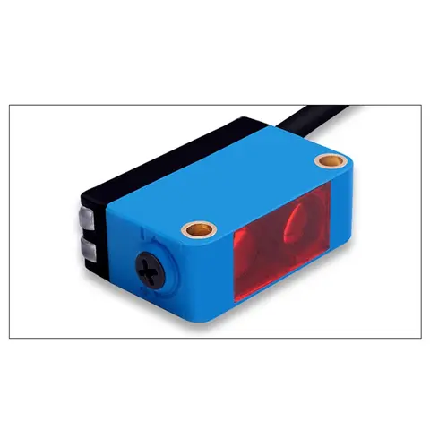
BGS-CX441 / BGS-CX442 Background Suppression Photoelectric Sensor
Wire-adjustable BGS sensor with 2 mm or 15 mm spot, 10-300 mm range, published black/white differential distance.
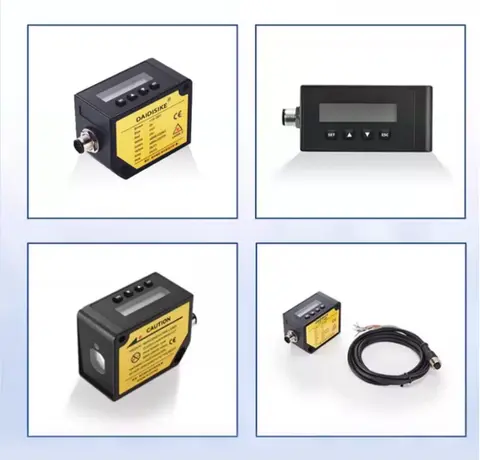
DDA-Y & DDB-Y Industrial Laser Distance Sensor (Phase-Shift)
Phase-shift laser distance sensors: 0.2-100 m range, millimeter accuracy, RS485 Modbus RTU, switching or analog output.
Related Products in Relay & Timer Modules
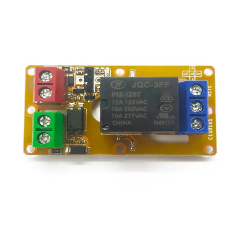
A1J0101 Economical Input Amplifier Module
Optocoupler-isolated input amplifier that turns a low-voltage signal into a 250V AC / 10A relay output.
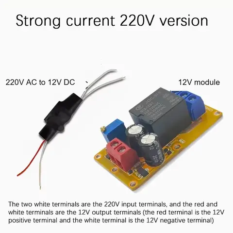
B2J0101 Economical Power-up Delay Module
Low-cost power-up delay relay module with a 2-30 second adjustable delay and no trigger input required.
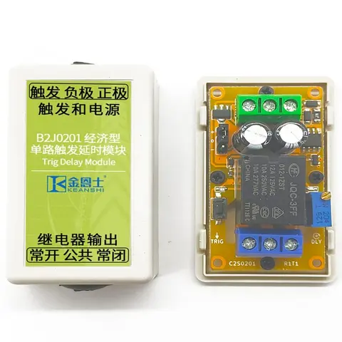
B2J0201 Economical Trigger Delay Module
Level-triggered delay relay module with jumper-selectable high/low trigger and a 2-30s adjustable delay.
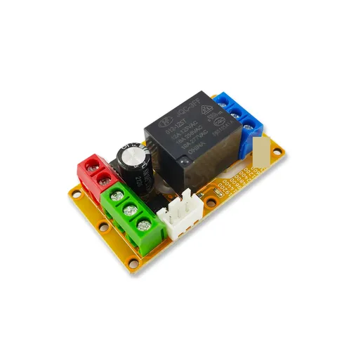
B2J0302 Enhanced Single MODBUS-485 I/O Module
Enhanced single-channel MODBUS-RTU/RS-485 I/O module: 1 digital input, 2 analog inputs, 1 relay or transistor output, AT command support and a 5V sensor supply — the successor to the discontinued B2J0301.