
E4J0101 Easy Multifunctional Trigger Delay Module
ASIC-based delay relay with ~100 templates, ~1,000 delay modes, and optional wireless remote trigger.
 🔍 Click to enlarge · 1/8
Technical Specifications
| Supply voltage | 5V DC: 4.8-5.2V; 9V DC: 8.5-11V; 12V DC: 11-14V; 18V DC: 16-20V; 24V DC: 20-28V |
|---|---|
| Power supply ripple | Less than 1Vp-p |
| Supply current | Less than 200mA (about 40mA typical with the relay energized) |
| Output stress, relay type | DC 30V or AC 0-220V, 8A |
| Output stress, transistor type | DC 12-48V, 8A |
| Trigger input | DC 0-30V |
| TTL communication port | Less than 5Vp |
| Output isolating voltage, relay type | Less than 250V |
| Output isolating voltage, transistor type | Less than 130V |
| Operating temperature | -20 to 60°C |
| Absolute max. supply voltage | 5V DC: 5.3V; 9V DC: 11.5V; 12V DC: 15V; 18V DC: 22V; 24V DC: 30V |
| Self-resettable fuse | DC 60V, 500mA |
| Absolute max. output stress, relay type | AC 250V, 10A |
| Absolute max. output stress, transistor type | DC 55V, 10A |
| Storage temperature | -40 to 85°C |
| Absolute max. trigger input | DC 50V |
| Absolute max. TTL communication port | Less than 5.5Vp |
| Absolute max. input isolating voltage | DC 1000V, 60s (type test only) |
| Absolute max. output isolating voltage, relay type | DC 1000V, 60s (type test only) |
| Absolute max. output isolating voltage, transistor type | DC 250V, 60s (type test only) |
| Relay mechanical life | More than 100,000 times (more than 10,000 times under heavy load) |
| Delay templates | About 100 basic templates x 4 polarity combinations (about 1,000 delay modes) |
| Delay time range, A and C | 0-999 x selectable unit (10ms / 100ms / 1s / 10s / 1min / 10min / 1h / 10h); a setting of 0 is treated as 10ms |
| Loop count, L | 0-9999 (0 = unlimited) |
| Delay accuracy | 1.5% factory (full temperature range); 0.1% after USB PC calibration (0.05% with fine calibration) |
| TTL serial port | 1500 baud, no parity, 1 stop bit, AT command protocol |
| Module dimensions (L x W x H) | 66mm x 41mm x 20mm, tolerance ±5% |
| Terminal pitch | 5.08mm |
| Terminals and controls | 7 screw terminals, 4 buttons, 1 digit display, 3 LED indicators, 1 USB port, 1 TTL port |
Overview
The E4J0101 is an ASIC-based, easy-to-use multifunctional digital trigger delay relay module for machine builders, panel builders, and automation integrators who want one field-configurable timer to replace a shelf of separate time relays. It accepts one high-voltage optocoupler-isolated digital trigger input and drives one output, relay or transistor depending on model, and can be configured entirely on-board with a digit display and 4 keys, or from a PC over USB or TTL serial.
About 100 basic delay templates across five groups, switching, delay-then-break, delay-make-then-break, cyclic delay, and counting delay, combine with input/output polarity inversion to form roughly 1,000 distinct delay modes. Factory delay accuracy is 1.5% across the full temperature range, tightened to 0.1% (0.05% with fine calibration) after PC calibration over USB. Select models add wireless remote triggering, and firmware is field-upgradeable to add new functions.
Features & Benefits
One Module Replaces a Shelf of Time Relays
About 100 independent delay templates are built in across five groups: switching (5 templates), delay-then-break (40), delay-make-then-break (34), cyclic delay (17) and counting delay (8). Each template's input and output polarity can be inverted independently, giving 4 submodes per template, and every trigger-accepting mode can also be set to trigger once at power-up with a defined output state before that first trigger. The result is roughly 1,000 distinct delay modes from one part number, so a panel that used to carry on-delay, off-delay, interval, cyclic and counting timers as five separate items now carries one.
Set the Delay in the Field With Four Buttons, No PC and No PLC
A 4-digit display and the M / S / + / - keys expose the whole configuration on the board: F--0 input-output mode, F--1 delay template, P--A and P--C delay times, P--L loop count. Delay A and C are each 0-999 multiplied by a selectable unit of 10 ms, 100 ms, 1 s, 10 s, 1 min, 10 min, 1 h or 10 h, which spans 10 ms to thousands of hours without changing hardware, and loop count L runs 0-9999. Long-press M to unlock, adjust, long-press M to save. A commissioning engineer can retime a machine on the spot instead of pulling the timer out to reset a dial.
1.5% Out of the Box, 0.1% After You Calibrate It Yourself
The ASIC timebase holds 1.5% delay accuracy across the entire -20 to 60 C operating range, with none of the temperature drift of an RC-based timer. Plug the module into a PC over USB and the host software calibrates it to 0.1%, or 0.05% with fine calibration: the calibration value runs 0-100 (default 50), each step is about 0.05%, for a total trim range of about +/-2%. On a 60 s cycle that is the difference between about +/-0.9 s and about +/-0.06 s, and it is a field adjustment rather than a factory return.
Noise Immunity Measured at Twice the Industrial Requirement
IEC61000-6-2 asks for 1 kV EFT; the E4J0101 is measured at 2000 V EFT (5 kHz, 2 min, all terminals) with normal operation retained, and survives 4 kV EFT without permanent damage. ESD is measured at 4 kV on all terminals with normal operation, and the supply survives a 1 kV surge to ground. The digital trigger input sits behind a real optocoupler measured at 1500 V DC (type test DC 1000 V for 60 s). That is headroom for contactor-heavy cabinets and long sensor runs; for inputs that see frequent, closely-spaced pulse trains, order the reinforced input-resistor version with the XS suffix.
Safety Clearances Verified, Not Assumed
Creepage from the relay terminals (primary side) to the logic side measures more than 6.05 mm against the IEC60950 requirement of 6 mm at pollution degree 3, material group IIIa/IIIb, and clearance from the optocoupler input and relay terminals to the logic side measures more than 2.1 mm against a 2 mm requirement. The PCB carries dedicated creepage slots on the high-voltage side. The supply adds reverse-polarity, overcurrent and surge protection with a DC 60 V / 500 mA self-resettable fuse, so a miswired supply is an inconvenience rather than a dead module. Certification documents are available on request.
Optional Wireless Remote Trigger, or Trigger It From a PLC Over Serial
Remote-control versions pair to a supplied remote by long-pressing S until the display stops flashing; one key press is a clean trigger pulse of about 500 ms, which removes a wiring run wherever a button is awkward to reach. Non-remote versions instead expose a TTL serial port (5 V level, 1500 baud, no parity, 1 stop bit): AT returns OK, AT+TRG fires a trigger of about 500 ms, AT+PIN? reads the input level, and AT+OUT= / AT+OUT? write and read the output directly when template 0200 (serial/USB-controlled relay) is selected. The USB port enumerates as a virtual COM port and speaks the same AT set.
Relay or Transistor Output, Five Supply Voltages, One 66 x 41 x 20 mm Footprint
The same board runs on 5 V, 9 V, 12 V, 18 V or 24 V DC (first digit of the order code) and draws under 200 mA, about 40 mA with the relay energized. Choose the arc-suppressed relay output for DC 30 V or AC 0-220 V at 8 A with more than 100,000 mechanical operations, or the open-drain transistor output for DC 12-48 V at 8 A with a built-in 10 A freewheeling diode that drives inductive loads directly and silently at high cycle rates. Same 66 x 41 x 20 mm body, same 5.08 mm terminal pitch, so a change of supply rail or output type is an order-code change, not a redesign.
Upgradeable Firmware, and a Documented Path to Cheaper Volume Production
Firmware is field-upgradeable over USB in three variants, normal (NF), quick-configuration (QCF) and customized (CF), so a module already installed can gain new functions. And once a trial mode is proven, the DAIDISIKE Easylight process fixes that exact delay behaviour into the lower-cost B2J0601 for mass production; every E4J0101 delay mode is reproducible on it, cutting total cost of ownership by up to 70% at million-unit volumes. Prototype on the flexible module, ship on the economical one.
Applications
Models & Ordering Information
Ordering Model
How to Select
- Bare-board supply, enclosure and DIN-rail mounting are ordering options for this B2J/E4J module. Specify what is included on the quotation; do not assume an enclosure or mounting kit is supplied as standard.
- Choose the relay output (default M31, 12V) for general AC or DC load switching up to DC 30V or AC 0-220V at 8A, rated for more than 100,000 mechanical operations.
- Choose the transistor (open-drain) output, rated 12-48V DC with a built-in 10A freewheeling diode, for driving inductive loads directly; use power-on sequencing since transistor outputs can pulse briefly (about 100ms) at power-up or power-down even without a trigger.
- Add the remote-control option (for example M312) when a push button is hard to wire or an operator needs to trigger the module from a distance; note that the remote-control configuration replaces the TTL serial port (M311 = no remote, has TTL; M312 = has remote, no TTL).
- Pick one of the five delay-template groups, switching, delay-then-break, delay-make-then-break, cyclic delay, or counting delay, for the desired behavior, then use input/output polarity inversion to derive the exact trigger edge and output logic needed.
- This model has no RTC/real-time clock and no voltage-threshold or analog measurement function; its trigger is strictly a digital (high/low level, edge) optocoupler-isolated input. Choose the E4J0102 for voltage-threshold detection or calendar-based clock triggering, or the E4J0103 for two independent or linked relay outputs.
- For volume production, once a delay mode is proven on the E4J0101, ask about migrating it to the lower-cost B2J0601, which can reproduce the same delay behavior at reduced size and cost for large-quantity runs.
- Order the reinforced input-resistor version (suffix XS) if the digital input will see frequent, closely-spaced EFT pulses rather than the sparse pulse trains the standard EFT rating was tested against.
📘 Need the full method? NPN vs PNP Sensor Outputs Explained
When NOT to specify the E4J0101 — and what to use instead
You need calendar or time-of-day triggering, or a built-in real-time clock
Why not: E4J0101's own selection guide states it has no RTC and no voltage-threshold or analog measurement function. Its trigger is strictly a digital, optocoupler-isolated level or edge input.
Use instead: E4J0102, the clock / RTC delay module.
You need two independent or linked output channels from one unit
Why not: E4J0101 is single-channel: one optocoupler-isolated trigger input and one relay or transistor output per module.
Use instead: E4J0103, the dual-channel trigger delay module.
You need both the wireless remote-control feature and the TTL serial port on the same unit
Why not: The third digit of the ordering code makes them mutually exclusive: one option gives no remote but a TTL serial port, the other gives remote but no TTL port. A single unit cannot have both.
Use instead: Order separate units for each need, or use serial / USB control alone if remote triggering is not essential.
Wiring the trigger input directly to a source producing frequent, closely-spaced EFT pulses — right at a solenoid or brush-motor terminal
Why not: The standard EFT rating on the input port was measured against sparse pulse groups minutes apart, per the manual's own reliability notes. Frequent pulses can overload the input resistor and cause rapid input failure.
Use instead: Order the reinforced input-resistor version for that duty — tell us the load and we will confirm the correct ordering code.
A high-volume production run where per-unit cost matters more than field configurability
Why not: E4J0101's flexible design — digit display, 4 keys, USB, TTL port and roughly 1,000 modes — carries cost you stop needing once a specific delay behaviour has been proven out.
Use instead: Once the mode is proven, migrate it onto the lower-cost fixed-function B2J0601 for mass production. Ask us about this.
A safety-related delay, such as timing a guard release or part of an emergency-stop sequence
Why not: Per its own FAQ it is a configurable delay / timer relay module, not a safety relay with forcibly-guided contacts and feedback monitoring. It carries no Type / SIL / PL rating.
Use instead: DA31 Emergency-Stop Safety Relay Module or DQSRN Safety Relay Module.
Specifications we do not publish yet
We only publish a figure once we are confident it is true. The items below are still being validated through further testing and real-world customer feedback, so for now we would rather leave them open than guess. If one of them matters to your design, ask us for the latest validated status.
- Electrical (load-switching) contact life under the rated 8 A load, as distinct from the published mechanical life.
- Relay brand and model number.
- Ingress protection (IP) rating.
- MTBF.
- Operating and storage relative humidity range.
- Terminal wire gauge and screw torque.
- Firmware-update failure and rollback behaviour — the risk that a failed USB upgrade leaves the unit unusable is not documented.
- Certification status of the standard production unit. The manual references a CQC voluntary certificate, but its own footnote states that certificate applies only to a specific reinforced-wiring-terminal version, not the module as generally sold — so we do not claim it for the standard unit. Certification documents are available on request.
Frequently Asked Questions
How many delay modes does the E4J0101 support?
How accurate is the E4J0101's delay timing?
Can I configure the E4J0101 without a computer?
Does the E4J0101 support wireless remote control?
What is the difference between the relay and transistor output versions?
How is the E4J0101 different from a safety relay?
What is the difference between the E4J0101, E4J0102, and E4J0103?
Is the E4J0101 certified to any safety or EMC standard?
Related Categories and Example Products
Explore other functions that may be needed in a machine or line. The products below are category examples, not pre-validated electrical or safety combinations. Confirm each interface and application separately: Proximity Sensors · Photoelectric Sensors · Laser Distance Sensors
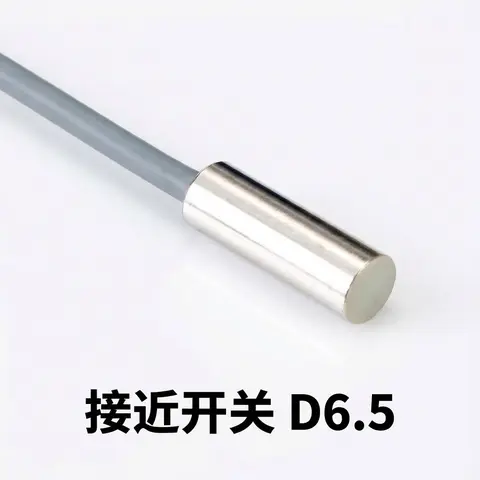
D6.5 Series Inductive Proximity Sensors (Ultra-Short 18mm / Y-Type / 35mm / 45mm)
6.5mm-diameter inductive proximity sensors for tight-clearance mounting where M8 sensors won't fit.
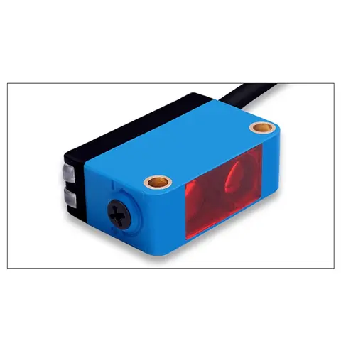
BGS-CX441 / BGS-CX442 Background Suppression Photoelectric Sensor
Wire-adjustable BGS sensor with 2 mm or 15 mm spot, 10-300 mm range, published black/white differential distance.
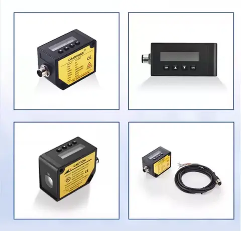
DDA-Y & DDB-Y Industrial Laser Distance Sensor (Phase-Shift)
Phase-shift laser distance sensors: 0.2-100 m range, millimeter accuracy, RS485 Modbus RTU, switching or analog output.
Related Products in Relay & Timer Modules
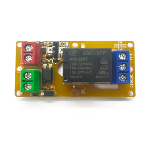
A1J0101 Economical Input Amplifier Module
Optocoupler-isolated input amplifier that turns a low-voltage signal into a 250V AC / 10A relay output.
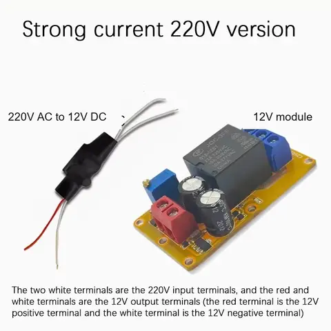
B2J0101 Economical Power-up Delay Module
Low-cost power-up delay relay module with a 2-30 second adjustable delay and no trigger input required.
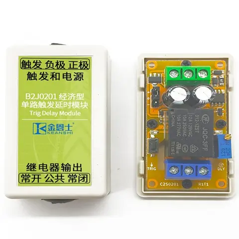
B2J0201 Economical Trigger Delay Module
Level-triggered delay relay module with jumper-selectable high/low trigger and a 2-30s adjustable delay.
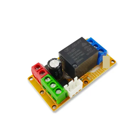
B2J0302 Enhanced Single MODBUS-485 I/O Module
Enhanced single-channel MODBUS-RTU/RS-485 I/O module: 1 digital input, 2 analog inputs, 1 relay or transistor output, AT command support and a 5V sensor supply — the successor to the discontinued B2J0301.