
E4J0103 Easy Multifunctional Dual-Channel Trigger Delay Module
Two relay/transistor outputs, independent or linked via four modes, with 0.01% delay accuracy and ~1000 delay modes.
 🔍 Click to enlarge · 1/10
Technical Specifications
| Supply voltage | 5V type: DC 4.8-5.2V; 9V-28V type: DC 8.5-29V; 80V-250V type: AC or DC 75-260V |
|---|---|
| Power supply ripple | Less than 1Vp-p |
| Supply current | Less than 200mA |
| Trigger input stress | DC 0-30V |
| TTL communication port | Less than 5Vp |
| Output stress, relay type | DC 30V or AC 0-220V, 8A |
| Output stress, transistor type | DC 12-48V, 8A |
| Output isolating voltage, relay type | Less than 250V |
| Output isolating voltage, transistor type | Less than 130V |
| Operating temperature | -20 to 60°C |
| Absolute max. supply voltage | 5V type: DC 5.3V; 9V-28V type: DC 30V; 80V-250V type: AC or DC 265V |
| Self-resettable fuse | DC 60V, 500mA |
| Absolute max. trigger input | DC 50V |
| Absolute max. TTL communication port | Less than 5.5Vp |
| Absolute max. output stress, relay type | AC 250V, 10A |
| Absolute max. output stress, transistor type | DC 55V, 10A |
| Absolute max. input isolating voltage | DC 1000V, 60s (type test only) |
| Absolute max. output isolating voltage, relay type | DC 1000V, 60s (type test only) |
| Absolute max. output isolating voltage, transistor type | DC 250V, 60s (type test only) |
| Relay mechanical life | More than 100,000 times (more than 10,000 times under heavy load) |
| Storage temperature | -40 to 85°C |
| Delay templates per channel | About 100, across five groups (switching, delay-then-break, delay-make-then-break, cyclic, counting) |
| Combined delay modes | About 1000, via input/output polarity reversal of each template |
| Factory-default delay accuracy | 0.01% (one part in ten thousand), full temperature range |
| Delay time A/C setting range | 0-999 x selectable unit (10ms/100ms/1s/10s/1min/10min/1h/10h) |
| Cycle count L setting range | 0-9999 (0 = unlimited) |
| Analog threshold range and resolution | 0-30V, set in 0.01V steps via the U--H/U--L menus |
| RTC accuracy (RTC option) | Typical 0.25 sec/day (about 91 seconds per 365-day year); maximum 0.5 sec/day (about 183 seconds per 365-day year) |
| RTC scheduled trigger points (RTC option) | Up to 8 (H--0 to H--7) |
| ESD immunity (measured, EN61000-4-2) | 4kV, all terminals: normal operation (A) |
| EFT immunity (measured, EN61000-4-4) | 2kV/5kHz/2min, all terminals: normal operation (A); 4kV/5kHz/2min: no permanent damage (C) |
| Surge immunity (measured, EN61000-4-5) | 1kV to ground, all terminals: no permanent damage (C) |
| Mechanical dimensions (L x W x H) | 96mm x 56mm x 20mm, tolerance ±5% |
| Terminal pitch | 5.08mm |
| Terminals and controls | 17 screw terminals, 5 buttons, 2 digit-tube displays, 6 LED indicators, 1 USB port, 1 buzzer |
Overview
The E4J0103 is a multifunctional dual-channel digital delay module built around a dedicated ASIC, for machine builders and panel integrators who need two independently timed or jointly linked output channels instead of wiring several separate timers and interlock relays. It combines three optocoupler-isolated digital trigger inputs (channel 0 trigger, channel 1 trigger, and a dedicated reset input) with two non-isolated analog voltage inputs (0-30V) and two relay or transistor outputs, and is configured on-device with a digit-tube display and buttons, or over a USB connection to a computer.
The two output channels can run independently or be linked through four linkage categories - simultaneous trigger, sequential trigger, alternating trigger, and mutual-follow (same/interlock/mutual-block) - plus a dedicated motor forward/reverse mode for two-limit-switch actuator control. Each channel offers about 100 independent delay templates across five groups (switching, delay-then-break, delay-make-then-break, cyclic, and counting), and with input/output polarity reversal this yields about 1000 delay modes in total. Factory-default delay accuracy is 0.01% (one part in ten thousand) across the full temperature range, and select models add a high-precision RTC, RS-485 (MODBUS-RTU/ASCII), or wireless remote control.
Features & Benefits
Two Timed Outputs on One 96 x 56 mm Board - Independent or Linked by a Single Digit
Each output carries its own delay template, delay times A and C and cycle count L, so a single 96 x 56 x 20 mm module does the job that normally takes two or three separate time relays plus interlock relays and all the wiring between them. One digit of the F--0 menu decides everything: 0 leaves the channels fully independent, while 1 to 9 makes one channel follow the other's trigger, delay end, make or break - and when the condition is met the linked channel receives an approximately 500 ms valid trigger level. Panel space, terminal count and commissioning time all collapse to a single device.
Four Linkage Categories Plus Motor Forward/Reverse - No External Interlock Circuit
Linkage covers simultaneous trigger, sequential trigger, alternating trigger and mutual-follow, the last with three sub-options set on channel 1: same (channel 1 mirrors channel 0), interlock (a trigger on one channel instantly resets the other, the classic forward/reverse case) and mutual-block (a channel cannot be triggered while the other is timing, for mutually exclusive loads). Sequences that cannot be decomposed into two independent actions get the dedicated motor forward/reverse mode (9000-9005, relay-output models): trigger DI0 runs the motor, DI1 is the forward limit and the reset input is the reverse limit, with forward energising relay 0 and reverse relay 1, for ordinary forward/reverse sequencing. This process-logic feature does not remove the need for correctly rated motor switching, protective interlocking or independent personnel-safety measures.
About 1000 Delay Modes Set with Five Buttons - No PLC, No Programming
Each channel picks from about 100 delay templates in five groups (switching, delay-then-break with 40 variants, delay-make-then-break with 34, cyclic with 18 and counting with 8), and reversing input and output polarity turns every template into four sub-modes, for about 1000 modes in total. Times A and C are set 0-999 in units of 10 ms, 100 ms, 1 s, 10 s, 1 min, 10 min, 1 h or 10 h - from 10 ms right up to 999 x 10 h - and the cycle count L runs 0-9999, with 0 meaning unlimited. It is all done on the two digit tubes and five keys (C / M / S / + / -), so no PLC, no software and no programmer are needed on site.
Three Ways to Trigger It, Plus a Dedicated Reset Input
Three high-voltage optocoupler-isolated digital inputs (DC 0-30 V) take dry contacts, push-buttons or PNP sensors. The third of them (terminal 2, DI2) is not a trigger but a true reset: the moment it sees the level configured by the second digit of F--0, that channel's delay stops immediately - an emergency brake or manual reset that does not wait for the timer to expire. Two non-isolated analog inputs (DC 0-30 V) turn a raw voltage into a trigger as well. The analog side works two ways: hysteresis (Schmitt) mode when the high threshold is at or above the low one, which kills contact bounce and false triggers, or range mode when the high threshold is below the low one, which fires when the voltage sits between the two limits - a ready-made clamp or voltage alarm. Thresholds are set to 0.01 V in the U--H / U--L menus, and holding the C key shows the live input voltage in 0.01 V steps so you can read the real level before choosing the trip point.
0.01% Delay Accuracy Across the Whole Temperature Range, and an RTC That Barely Drifts
Factory-default delay accuracy is 0.01% - one part in ten thousand - over the full -20 to 60 C operating range, not just at room temperature. RTC models add a battery-backed real-time clock with typical drift of 0.25 s/day (about 91 seconds per year, 0.5 s/day worst case) and no meaningful temperature coefficient, so a scheduled trigger set today is still on time next season. Up to 8 time points (H--0 to H--7) can be stored, each field wildcarded for yearly, monthly, daily, quarterly, weekday, weekend, morning, afternoon, on-the-hour or on-the-minute matching.
USB, MODBUS and Firmware Upgrades - The Module Grows With the Job
Every unit enumerates over USB as a virtual COM port for setup and AT commands (AT+TRG to trigger a channel, AT+ADC? to read both analog inputs in mV, AT+PIN? to read the input levels), and firmware can be re-flashed - either the standard full-function build or a quick-adjust build that exposes only A, C and L so an operator cannot change the mode by accident. RS-485 models speak MODBUS-RTU and MODBUS-ASCII (default 9600 baud, even parity, 1 stop bit, address 0x02, product ID 0x4103) with coils for TRG0, TRG1, RST, OUT0 and OUT1, a SAFELCK register that must be unlocked with UL before sensitive settings can be written, and a host-configurable 1-65535 ms input filter for noisy signal lines.
Built and Measured to Industrial Limits, Not Just Specified to Them
Measured 2000 V EFT immunity is twice the 1 kV that IEC61000-6-2 demands of industrial equipment (4 kV causes no permanent damage), ESD is 4 kV on all terminals with normal operation, and 1 kV surge to ground causes no permanent damage. On the high-voltage side the creepage is measured at more than 6.05 mm against a more than 6 mm requirement and clearance at more than 2.1 mm against more than 2 mm (IEC60950, pollution degree 3), with proper slots cut in the PCB. Add reverse-polarity, overcurrent and surge protection, a self-resettable DC 60 V / 500 mA fuse, and an XS-suffix reinforced-input variant for sites with dense pulse trains wired straight into the inputs.
Relay or Transistor Output, Your Call at Order Time
Relay models switch AC 0-220 V or DC 30 V at 8 A through arc-suppressed NC / COM / NO contacts, with mechanical life beyond 100,000 operations (more than 10,000 under heavy load). Transistor models are open-drain for DC 12-48 V at 8 A with a built-in freewheeling diode, so an inductive load can be driven directly, silently and without contact wear. Mixed relay-plus-transistor builds are available too, and the choice is just one digit in the six-digit sub-model code.
Applications
Models & Ordering Information
Ordering Model
How to Select
- Bare-board supply, enclosure and DIN-rail mounting are ordering options for this B2J/E4J module. Specify what is included on the quotation; do not assume an enclosure or mounting kit is supplied as standard.
- Choose the E4J0103 over single-channel modules such as the E4J0101 or E4J0102 whenever two channels need to work together - simultaneous trigger, sequential trigger, alternating trigger, mutual-follow, or motor forward/reverse - or when RS-485/MODBUS bus control is required.
- Choose the relay output for general AC or DC load switching up to DC 30V or AC 0-220V at 8A with more than 100,000 mechanical operations; choose the transistor (open-drain) output for fast, silent switching of 12-48V DC inductive loads up to 8A, and note it can briefly pulse on power-up/down so add power sequencing if the load is sensitive to that.
- Pick the supply voltage tier that matches the installation: 5V, 9V-28V, or 80V-250V AC/DC; 9V-28V DC with all-relay output (M211221) ships by default if nothing else is specified.
- Add the RTC option for scheduled, time-of-day triggering (up to 8 trigger points); add the RS-485/MODBUS option to join a PLC or SCADA network; add the wireless remote option for handheld triggering of either channel or the reset input.
- For motor forward/reverse control (roller shutters, retractable gates, valve actuators), use the dedicated motor forward/reverse mode (relay-output models only), which needs just one start/stop trigger and two limit-switch inputs.
- The 80V-250V AC/DC supply variant does not include household safety circuitry due to board space, so it must not be used in household settings or installed by non-professionals; fit a line filter and external fuse at the supply input.
- This is a general-purpose programmable delay/linkage module, not a safety-rated relay; for machine-guarding stop functions, pair it with a dedicated safety relay.
📘 Need the full method? NPN vs PNP Sensor Outputs Explained
When NOT to specify the E4J0103 — and what to use instead
Only one channel/output is needed, with no linkage to a second channel
Why not: The E4J0103 is built around two output channels with four linkage categories and a dedicated motor forward/reverse mode; a single-channel job pays for a second channel and linkage logic it will never use.
Use instead: E4J0101 (single-channel digital-trigger delay) or E4J0102 (single-channel analog/clock-trigger delay)
More than two linked/interlocked channels are required (three or more coordinated stages)
Why not: The E4J0103's linkage modes (simultaneous, sequential, alternating, mutual-follow) and its F--0 menu coordinate only its own 2 output channels; there is no way to chain linkage logic to a third channel through the same menu.
Use instead: E4J0206 (current ordering name; existing D4G0206 page address retained), a schematic-programmed micro PLC with 6 inputs / 4 outputs for ordinary multi-channel control logic, not a personnel-safety PLC
The application needs a machine safety stop function (e-stop, guard interlock)
Why not: The E4J0103's own selection guidance states it is a general-purpose programmable delay/linkage module, not a safety-rated relay (no Type/SIL/PL); its outputs are not OSSDs.
Use instead: DA31 Emergency-Stop Safety Relay Module or DQSRN Safety Relay Module - never use the E4J0103 in a machine safety function
The 80V-250V AC/DC supply variant is being considered for a household installation or installation by a non-professional
Why not: The datasheet states this supply variant omits household-safety circuitry (filtering, protection) due to board space, and must not be used in household settings or installed by non-professionals.
Use instead: the 5V or 9V-28V supply variant of the E4J0103 for low-voltage installations; use professional installation only for the 80V-250V variant
A long unattended RTC schedule must run with near-zero drift and no other timing reference
Why not: The E4J0103 RTC option drifts a typical 0.25s/day (about 91 seconds/year) and up to 0.5s/day worst case - adequate for calendar scheduling but not a precision timebase.
Use instead: pair with an external time-sync source for mission-critical scheduling; no tighter-drift sibling exists in this range
Specifications we do not publish yet
We only publish a figure once we are confident it is true. The items below are still being validated through further testing and real-world customer feedback, so for now we would rather leave them open than guess. If one of them matters to your design, ask us for the latest validated status.
- MTBF (mean time between failures)
- IP / ingress-protection rating
- RTC backup battery type, capacity and expected replacement interval
- Terminal wire gauge and screw-torque specification for the 5.08mm terminals
- Formal 3C/CE certification status and certificate number — certificate pending; documents available on request once issued
- Wireless-remote option: frequency band, range and pairing method
Frequently Asked Questions
Is the E4J0103 a safety relay or a programmable delay module?
How many delay modes does the E4J0103 support and how is it configured?
Can the two output channels work together, and how?
Does the E4J0103 support MODBUS-RTU and MODBUS-ASCII over RS-485?
What inputs, outputs, and protection does the E4J0103 provide?
Can the E4J0103 trigger outputs at a fixed time of day or wirelessly?
Is the E4J0103 certified to any safety or EMC standards?
Related Categories and Example Products
Explore other functions that may be needed in a machine or line. The products below are category examples, not pre-validated electrical or safety combinations. Confirm each interface and application separately: Proximity Sensors · Photoelectric Sensors · Laser Distance Sensors
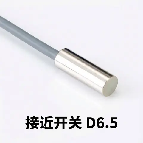
D6.5 Series Inductive Proximity Sensors (Ultra-Short 18mm / Y-Type / 35mm / 45mm)
6.5mm-diameter inductive proximity sensors for tight-clearance mounting where M8 sensors won't fit.
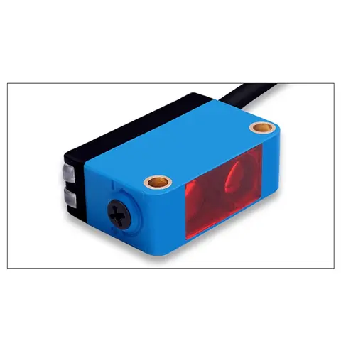
BGS-CX441 / BGS-CX442 Background Suppression Photoelectric Sensor
Wire-adjustable BGS sensor with 2 mm or 15 mm spot, 10-300 mm range, published black/white differential distance.
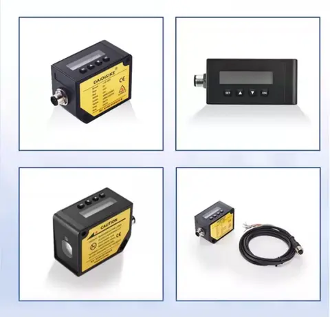
DDA-Y & DDB-Y Industrial Laser Distance Sensor (Phase-Shift)
Phase-shift laser distance sensors: 0.2-100 m range, millimeter accuracy, RS485 Modbus RTU, switching or analog output.
Related Products in Relay & Timer Modules
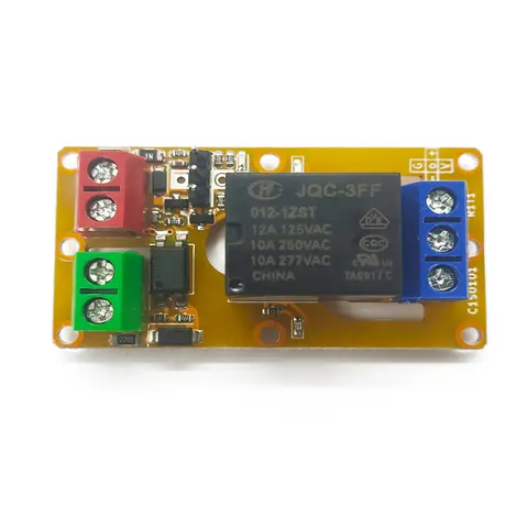
A1J0101 Economical Input Amplifier Module
Optocoupler-isolated input amplifier that turns a low-voltage signal into a 250V AC / 10A relay output.
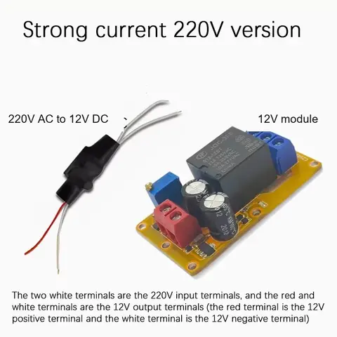
B2J0101 Economical Power-up Delay Module
Low-cost power-up delay relay module with a 2-30 second adjustable delay and no trigger input required.
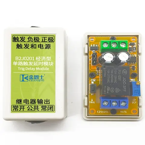
B2J0201 Economical Trigger Delay Module
Level-triggered delay relay module with jumper-selectable high/low trigger and a 2-30s adjustable delay.
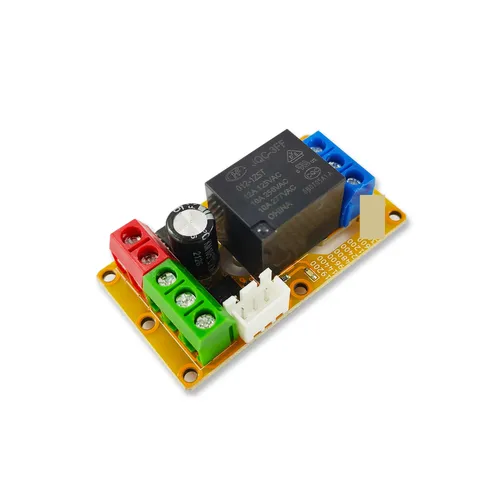
B2J0302 Enhanced Single MODBUS-485 I/O Module
Enhanced single-channel MODBUS-RTU/RS-485 I/O module: 1 digital input, 2 analog inputs, 1 relay or transistor output, AT command support and a 5V sensor supply — the successor to the discontinued B2J0301.