
D4G0206 Relay Module
Graphical schematic-programmed micro PLC module with 6 inputs and 4 relay/transistor outputs, no ladder logic required.
 🔍 Click to enlarge · 1/10
Technical Specifications
| Current ordering code | E4J0206 (confirmed); legacy page title/URL retained as D4G0206. |
|---|---|
| Type | Multi-functional intelligent programmable delay module (micro PLC), graphical schematic programming |
| Supply voltage | 11-24V DC, reverse-polarity protected, max 28V |
| Operating current | <=250mA running, <=35mA standby |
| Digital/analog inputs | 6 channels, 0-35V DC, non-isolated from supply |
| Outputs | 4 channels, relay or transistor (model dependent) |
| Relay output | Potential-free, 0-30V DC or 0-220V AC, max 8A |
| Transistor output | Sinking, 12-48V DC only (no AC), max 8A |
| Communication | B/A terminals, RS-485/TTL selectable |
| Operating temperature | -20C to 60C |
| Storage temperature | -40C to 80C |
| Input isolation | Non-isolated from supply. Historical 1500V input-isolation claim conflicts with the terminal description and is not assigned to this version. |
| Isolated output (tested) | 1000V DC |
| ESD (IEC61000-4-2) | 4kV, normal operation on all input terminals and power |
| EFT (IEC61000-4-4) | 2kV at 5kHz, normal operation; 4kV without damage (wireless/RTC options may briefly malfunction) |
| Creepage distance (IEC60950-2L/2N) | >=6mm, pollution degree 3, basic insulation from relay terminals to logic side |
| Clearance (IEC60950-2H) | >=2mm, pollution degree 3, basic insulation from relay terminals to logic side |
| EMC standard | IEC61000-6-1-2006, light-industrial and commercial environments |
| Dimensions (L x W x H) | 72mm x 88mm x 59mm |
Overview
Current ordering code: E4J0206. This page retains the historical D4G0206 title and URL for continuity; use E4J0206 on current inquiries and purchase documents. Confirm the relay/transistor version and any housing, rail-mounting, RTC or wireless options in the quotation.
The E4J0206 is a micro PLC-style programmable delay module that replaces stacks of fixed-function time relays and hard-wired relay logic panels. Instead of ladder logic, it is programmed by drawing a schematic in host-computer software, so engineers without PLC training can build timing, counting and interlock logic and load it onto a compact industrial module.
It provides 6 non-isolated digital/analog inputs (0-35V DC) and 4 relay or transistor outputs rated up to 8A each, communicates over RS-485 or TTL (selectable) for Modbus networking, and runs from an 11-24V DC reverse-protected supply (max 28V) drawing no more than 250mA running and 35mA standby.
Features & Benefits
Draw the logic, don't write it - no ladder, no C, no PLC course
Draw the control sequence as a schematic in the host-PC software and download it using the supported interface. Confirm the software, module version and required programming/commissioning procedure. Changing a sequence may avoid rewiring in some applications, but terminal assignments and machine behavior must still be checked.
6 in / 4 out in 72 x 88 x 59mm - one part replaces a row of time relays
Six 0-35V DC input channels and four outputs sit in a housing the size of your palm. Each output can run its own delay, timing, counting or interlock, and channels can be linked together, so a job that used to need four or five separate time-delay relays plus the interlock wiring between them collapses into one part - fewer terminals, fewer wires, fewer failure points, one line on the BOM.
Select the output stage and load rating together
The catalogue lists relay contacts up to 8A at the stated voltage range. Select the actual relay or transistor version against load type, inrush, duty and suppression requirements; the headline current does not guarantee direct switching of every contactor or solenoid, nor eliminate every need for an interface relay.
Analog goes straight in - the AI card comes off the bill
Any of the six channels accepts an analog voltage as well as a dry contact, so a temperature/humidity transmitter, a pressure transmitter or a raw battery voltage wires directly to A0-A5 and is compared against a threshold inside the module. No separate analog input card, no extra rail space, and up to 35V of headroom on the signal.
Relay or transistor output on the same logic platform
The catalogue lists relay and transistor output versions. Relay contacts and DC sinking transistor outputs have different terminal functions and permitted loads; verify the exact order code, wiring and current/duty limits. The stated 8A maximum is not a promise of interchangeability across all load conditions.
Three layers of power protection sized for real field wiring
The 11-24V DC supply specification (maximum 28V) lists reverse-polarity, transient and overcurrent protection. Follow the correct polarity and rated conditions; these protections are not permission to intentionally miswire or expose the module to unspecified surges.
Output suppression and durability evidence
The catalogue describes an output absorption component and a transient test claim. Match the actual output stage and external load suppression to the selected configuration; request the test conditions before treating a figure as a guaranteed lifetime or surge-survival result.
RS-485 / TTL edge node, with RTC and wireless as order-time options
The B/A terminals give RS-485 or TTL (selectable) for Modbus, so the module reports to a host PLC, an HMI touch panel or a gateway while still running its logic locally - the machine keeps working if the network drops. Add the RTC option and it runs to a time-of-day schedule (fixed start/stop, off-peak windows); add the wireless remote option and you get cable-free local control, which is what retrofit jobs usually need.
Applications
Models & Ordering Information
Current E4J0206 ordering model
How to Select
- Choose the E4J0206 over a fixed-function time-delay relay when the application needs more than a single on-delay/off-delay behavior; it is a freely programmable logic platform, not a single fixed timer.
- Choose the E4J0206 over a plain relay module when the application needs logic between input and output, not just a direct pass-through or simple trigger.
- For a 6-input/4-output task, E4J0206 offers the catalogue's graphical logic and interface options. Compare the required instruction functions, response, software and load limits with the application; do not infer additional I/O from wider-series specifications.
- Add the RTC option if the application needs scheduled operation, such as fixed start/stop times or time-segmented control.
- Add the wireless remote option if the application needs cable-free local or remote operation.
- Use the standard configuration (digital input + relay output + RS-485) for wired logic control with no scheduling or remote-control requirement.
- Select relay output for AC contactors, solenoid valves and mixed AC/DC loads; select transistor output for DC-only loads that need high-frequency switching.
- Order enclosure, bare-board or rail-mounting options explicitly; a product photograph does not establish what is included in the standard shipment.
📘 Need the full method? NPN vs PNP Sensor Outputs Explained
When NOT to specify the D4G0206 — and what to use instead
Fixed plug-and-play delay/timer behavior is wanted with no programming step
Why not: The E4J0206 has no default timing behavior out of the box - the control sequence must be drawn as a schematic in host-computer software and downloaded before first use.
Use instead: E4J0101 or B2J0601 (fixed-function delay/timer relay, ready to use without programming)
More than 6 inputs or 4 outputs are needed on a single board
Why not: The current E4J0206 configuration is documented with 6 digital/analog inputs and 4 digital outputs. Other models in a wider programmable-module family must not be treated as selectable I/O counts for this model.
Use instead: a full-size PLC, or multiple E4J0206 units networked over its RS-485/TTL port
The application needs hard real-time or safety-rated logic (e-stop, guard interlock, SIL/PL-rated stop function)
Why not: The E4J0206 carries no safety rating (no Type/SIL/PL); it is a general-purpose schematic-programmed micro PLC, not a certified safety controller, and its outputs are not OSSDs.
Use instead: Select and validate suitable safety logic for the actual safety function. DA31 and DQSRN are separate candidates requiring their own exact input/function documentation; neither is automatic approval of the complete circuit.
No PC or configuration software is available on site to set or view parameters
Why not: All E4J0206 logic is authored in host-computer software and downloaded over the B/A terminals; the base module has no digit display or keypad for stand-alone on-device programming.
Use instead: E4J0101 / E4J0102 / E4J0103 (on-board digit-tube display and keys for standalone field setup)
Only a single simple on-delay or off-delay timing function is required
Why not: Drawing and downloading a schematic for one basic timing function is more setup effort than the job needs; the E4J0206 is built for multi-channel or interlocked logic, not as a single-timer replacement.
Use instead: E4J0101 or B2J0601 (fixed-function delay/timer relay)
Specifications we do not publish yet
We only publish a figure once we are confident it is true. The items below are still being validated through further testing and real-world customer feedback, so for now we would rather leave them open than guess. If one of them matters to your design, ask us for the latest validated status.
- Relay mechanical life / switching-cycle rating (not stated for this model, unlike sibling delay modules)
- MTBF (mean time between failures)
- IP / ingress-protection rating of the bare board or optional enclosure
- Surge immunity (EN61000-4-5) rating - only ESD and EFT figures are currently published
- Accuracy/drift figures for the optional RTC add-on (not published for this model)
- Wireless-remote option: frequency band, range and pairing method
- Terminal wire gauge and screw-torque specification
- Formal certification status and certificate number
- The historical 1500V input-isolation test claim conflicts with the documented non-isolated inputs; obtain the exact test configuration before publishing an isolation withstand value for this input stage.
- Exact output load category, inrush/current derating and test conditions for transient/lifetime claims; do not infer these from the 8A maximum alone.
Frequently Asked Questions
Should I order D4G0206 or E4J0206?
What is the E4J0206 micro PLC module?
How do I program the E4J0206 without PLC training?
What is the difference between the relay output and transistor output versions?
Does the E4J0206 support RS-485 and Modbus communication?
Can the E4J0206 run on a schedule or be triggered remotely?
How rugged is the E4J0206 against electrical disturbance?
Is the E4J0206 certified to international safety standards?
Related Categories and Example Products
Explore other functions that may be needed in a machine or line. The products below are category examples, not pre-validated electrical or safety combinations. Confirm each interface and application separately: Proximity Sensors · Photoelectric Sensors · Laser Distance Sensors

D6.5 Series Inductive Proximity Sensors (Ultra-Short 18mm / Y-Type / 35mm / 45mm)
6.5mm-diameter inductive proximity sensors for tight-clearance mounting where M8 sensors won't fit.
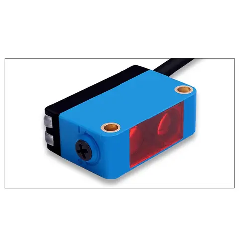
BGS-CX441 / BGS-CX442 Background Suppression Photoelectric Sensor
Wire-adjustable BGS sensor with 2 mm or 15 mm spot, 10-300 mm range, published black/white differential distance.
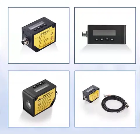
DDA-Y & DDB-Y Industrial Laser Distance Sensor (Phase-Shift)
Phase-shift laser distance sensors: 0.2-100 m range, millimeter accuracy, RS485 Modbus RTU, switching or analog output.
Related Products in Relay & Timer Modules
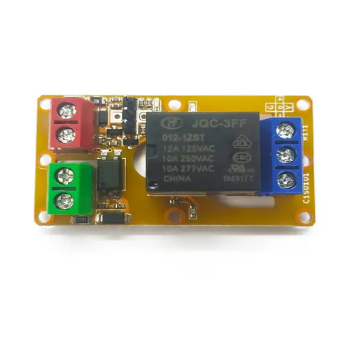
A1J0101 Economical Input Amplifier Module
Optocoupler-isolated input amplifier that turns a low-voltage signal into a 250V AC / 10A relay output.
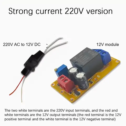
B2J0101 Economical Power-up Delay Module
Low-cost power-up delay relay module with a 2-30 second adjustable delay and no trigger input required.
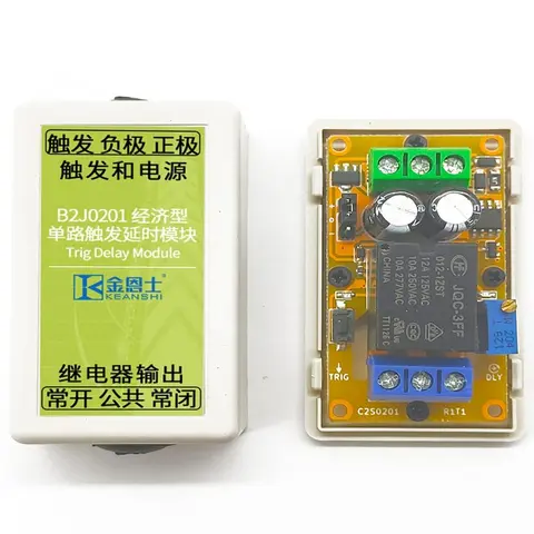
B2J0201 Economical Trigger Delay Module
Level-triggered delay relay module with jumper-selectable high/low trigger and a 2-30s adjustable delay.
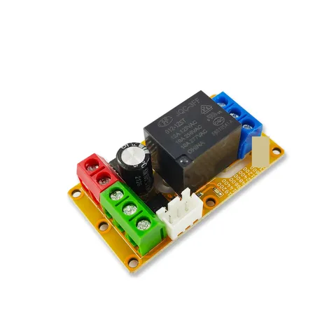
B2J0302 Enhanced Single MODBUS-485 I/O Module
Enhanced single-channel MODBUS-RTU/RS-485 I/O module: 1 digital input, 2 analog inputs, 1 relay or transistor output, AT command support and a 5V sensor supply — the successor to the discontinued B2J0301.