
B2J0601 Economical Intelligent Trigger Delay Module
26 delay modes, seconds to hours, 30 ppm accuracy, and built-in voltage-threshold detection in one button-set module.
 🔍 Click to enlarge · 1/6
Technical Specifications
| Supply voltage | 5V DC: 4.8-5.2V; 9V DC: 8.5-11V; 12V DC: 11-14V; 24V DC: 20-28V |
|---|---|
| Power supply ripple | Less than 1Vp-p |
| Supply current | Less than 50mA |
| Input stress (trigger terminal) | DC 0-30V |
| Output stress, relay type | DC 30V or AC 0-220V, 8A |
| Output stress, transistor type | DC 12-48V, 8A |
| Output isolating voltage, relay type | Less than 250V |
| Output isolating voltage, transistor type | Less than 130V |
| Operating temperature | -20 to 60°C |
| Absolute max. supply voltage | 5V DC: 5.3V; 9V DC: 11.5V; 12V DC: 15V; 24V DC: 30V |
| Self-resettable fuse | DC 30V, 500mA |
| Absolute max. input stress | DC 50V |
| Absolute max. output stress, relay type | AC 250V, 10A |
| Absolute max. output stress, transistor type | DC 55V, 10A |
| Absolute max. output isolating voltage, relay type | DC 1000V, 60s (type test only) |
| Absolute max. output isolating voltage, transistor type | DC 250V, 60s (type test only) |
| Relay mechanical life | More than 100,000 times (more than 10,000 times under heavy load) |
| Storage temperature | -40 to 85°C |
| Delay modes | 26 (3 units x 8 templates + 2 self-locking) |
| Delay time range | 0-255 units (second / minute / hour) |
| Long-term delay accuracy | 30 ppm |
| Trigger input voltage-threshold range | 0-30V, adjustable via potentiometer |
| PCB dimensions (L x W) | 55mm x 30mm, tolerance ±5% |
| Mounting hole spacing | 49mm (vertical) x 24.5mm (horizontal) |
| Terminal pitch | 5.08mm |
| Terminals and controls | 6 screw terminals, 1 button, 1 potentiometer, 1 jumper, 2 LED indicators |
Overview
The B2J0601 is a general-purpose intelligent delay relay module built around a dedicated smart delay ASIC, intended for machine builders and automation integrators who want a single module to cover most timing, sequencing, and voltage-threshold tasks instead of stocking several dedicated timers.
It combines 3 delay time units (second, minute, hour) with 8 basic delay templates for 24 modes, plus 2 self-locking modes, for 26 delay modes in total, all configured through a single button. Long-term delay accuracy reaches 30 ppm, delay time is adjustable from 0 to 255 units, and the trigger input doubles as a 0-30V voltage-threshold detector.
Features & Benefits
26 Delay Modes Replace a Shelf of Single-Purpose Timers
3 time units multiplied by 8 trigger/action templates give 24 delay modes, plus 2 self-locking modes, for 26 in total: high-level, low-level, rising-edge and falling-edge triggering, each as delay-then-break or as on-off-on cyclic toggling, plus edge latching. Instead of stocking a separate on-delay relay, a cyclic flasher and a latching relay, you stock one part number and pick the behaviour with the button.
Seconds, Minutes or Hours, 0 to 255 Units
The delay value is 0-255 and the unit itself is selectable as second, minute or hour, so the same board runs a 2-second warning-light flash interval or a 200-hour process soak. On the cyclic templates a setting of 0 is treated as 500 ms, giving a 1-second on-off interval with no extra hardware.
30 ppm Accuracy That Does Not Drift
The dedicated smart delay ASIC holds long-term accuracy to 30 ppm, about 0.3 seconds over a 3-hour cycle, and it does not drift with temperature, humidity or supply voltage anywhere in the -20 to 60 C range. An RC-based delay pot wanders with a cold morning or a sagging battery; this one repeats the same batch time every cycle.
One Button, No Programming, No PLC
Delay mode, time unit and delay time are all set with a single button, with no display, no software and no PLC. The indicator blinks 1-4 times at 0.5 s intervals for the time unit, pauses 1.5 s, then blinks 1-8 times for the template, so an electrician can confirm the active mode on a dark panel just by watching the LED.
Settings Lock Themselves Out Against Field Tampering
During normal operation the button is simply ignored, so a curious operator cannot change your timing. To configure, you hold the button while applying power and wait about 3 seconds for the relay to pull in, and the unlock lasts for that power cycle only. Holding past 10 seconds restores the factory default (mode 11: high-level trigger, break after 10 seconds), so a mis-set unit is recoverable on the spot.
The Trigger Input Is Also a Voltage Comparator
The trigger terminal accepts 0-30V DC and compares it against a threshold you dial in on the on-board knob, so it reads a battery, a level sender or an analog sensor directly instead of needing a separate comparator board. Set the delay to 0 on a level template and the module becomes a pure voltage detector. The input withstands DC 50V long term, and anything above 35V is always read as high.
Built with the High-Voltage Side in Mind
Measured PCB creepage from the relay terminals to the logic side is above 9.2 mm where IEC60950 asks for 6 mm, and clearance is above 2.2 mm where 2 mm is required (pollution degree 3, material group IIIa/IIIb). The supply carries reverse-polarity protection and a self-resettable DC 30V/500mA fuse, and the module runs through 1kV ESD and 500V/5kHz/2min EFT on all terminals per IEC61000-6-1-2016. Certification documents are available on request.
Factory-Preset and De-Featured for Volume Builds
Because the core is a dedicated ASIC, production orders ship with delay time, mode and voltage threshold already programmed, so your assembly line does no configuration at all. Terminals, the button, the indicators and the potentiometer can each be omitted to strip cost out of an embedded build, and you can send back a retail unit you have already dialled in and have the exact preset copied, skipping the specification back-and-forth.
Applications
Models & Ordering Information
Ordering Model
PDF & 3D CAD Downloads
Browse all downloadsB2J0601 Economical Intelligent Trigger Delay Module User Manual
Confirm the document and CAD file match the exact ordered version before installation or mechanical design. Contact us if your model is not listed.
How to Select
- Bare-board supply, enclosure and DIN-rail mounting are ordering options for this B2J/E4J module. Specify what is included on the quotation; do not assume an enclosure or mounting kit is supplied as standard.
- Choose the relay output (default M31, 12V) for general AC or DC load switching up to DC 30V or AC 0-220V at 8A, rated for more than 100,000 mechanical operations.
- Choose the transistor (open-drain) output for fast, silent, long-life switching of 12-48V DC inductive loads up to 10A; use power sequencing if the connected load reacts to a brief power-on pulse.
- Pick the supply voltage that matches your system: 5V, 9V, 12V, or 24V DC; 12V relay output (M31) ships by default if nothing else is specified.
- Set the delay time to 0 on a high-level or low-level template to use the module purely as a voltage-threshold detector, with no delay function.
- For volume orders, request factory-preset delay time, mode, and voltage threshold, or a simplified build without terminals, button, indicators, or potentiometer to reduce cost.
- This is a general-purpose timer, not a safety-rated device; for machine-guarding stop functions, use a dedicated safety relay instead.
📘 Need the full method? NPN vs PNP Sensor Outputs Explained
When NOT to specify the B2J0601 — and what to use instead
You need calendar or time-of-day scheduling, such as a fixed daily on/off time
Why not: B2J0601 has no real-time clock. All 26 modes are elapsed-time delays triggered by a level, an edge or a voltage threshold — never by a wall-clock schedule.
Use instead: E4J0102, the clock / RTC delay module.
You need two independent or linked delay channels from one module
Why not: B2J0601 is single-channel by ordering code: one trigger input and one relay or transistor output per unit.
Use instead: E4J0103, the dual-channel trigger delay module.
The system supply rail is 18 V DC
Why not: B2J0601's published supply options are 5 V, 9 V, 12 V and 24 V DC. Its operating-voltage table has no 18 V row, unlike some siblings.
Use instead: Confirm current voltage options with us, or use E4J0101, which is offered in an 18 V version.
You need to read the active mode or delay value at a glance, or log it
Why not: B2J0601 has no digit display. The active time unit and template are shown only as counted LED blink patterns (1-4 blinks, pause, 1-8 blinks), which take practice to read and cannot be logged over any port.
Use instead: E4J0101, which has a 4-digit numeric display plus USB / TTL readback.
A strong-interference site alongside motors, electromagnets or gas-discharge lamps
Why not: B2J0601 is tested to IEC 61000-6-1 light-industry levels (500 V EFT), not the 1 kV EFT of IEC 61000-6-2. Its own manual asks you to power it separately from and away from such loads above 1 W.
Use instead: Add filtering or an isolated EFT-resistant supply, or use E4J0101, measured at 2 kV EFT.
Specifications we do not publish yet
We only publish a figure once we are confident it is true. The items below are still being validated through further testing and real-world customer feedback, so for now we would rather leave them open than guess. If one of them matters to your design, ask us for the latest validated status.
- Electrical (load-switching) contact life under the rated 8 A load, as distinct from the published mechanical life.
- Relay brand and model number.
- Ingress protection (IP) rating.
- MTBF.
- Long-term drift and temperature coefficient of the 0-30 V voltage-threshold comparator. Only the 30 ppm timer accuracy is published.
- Operating and storage relative humidity range.
- Terminal wire gauge and screw torque.
- Certification status — the manual states none. Certification documents are available on request.
Frequently Asked Questions
What supply voltages and delay range does the B2J0601 support?
What are the 26 delay modes on the B2J0601?
Should I choose the relay output or the transistor output version?
What is the difference between a safety relay and this general-purpose delay relay?
Can the B2J0601 detect input voltage as well as create a delay?
Is the B2J0601 certified to any safety or EMC standards?
Related Categories and Example Products
Explore other functions that may be needed in a machine or line. The products below are category examples, not pre-validated electrical or safety combinations. Confirm each interface and application separately: Proximity Sensors · Photoelectric Sensors · Laser Distance Sensors
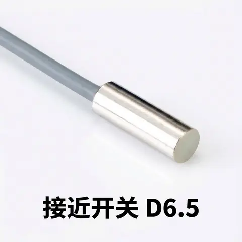
D6.5 Series Inductive Proximity Sensors (Ultra-Short 18mm / Y-Type / 35mm / 45mm)
6.5mm-diameter inductive proximity sensors for tight-clearance mounting where M8 sensors won't fit.
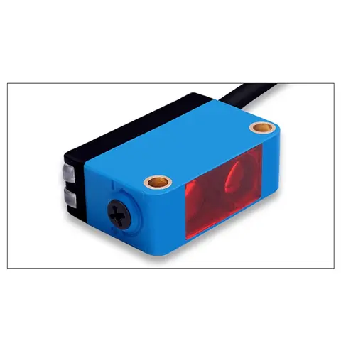
BGS-CX441 / BGS-CX442 Background Suppression Photoelectric Sensor
Wire-adjustable BGS sensor with 2 mm or 15 mm spot, 10-300 mm range, published black/white differential distance.
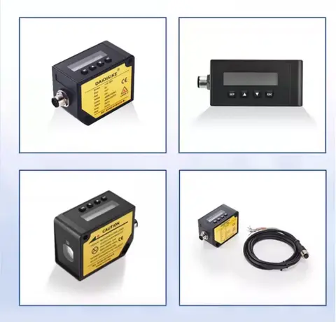
DDA-Y & DDB-Y Industrial Laser Distance Sensor (Phase-Shift)
Phase-shift laser distance sensors: 0.2-100 m range, millimeter accuracy, RS485 Modbus RTU, switching or analog output.
Related Products in Relay & Timer Modules
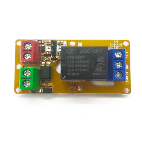
A1J0101 Economical Input Amplifier Module
Optocoupler-isolated input amplifier that turns a low-voltage signal into a 250V AC / 10A relay output.
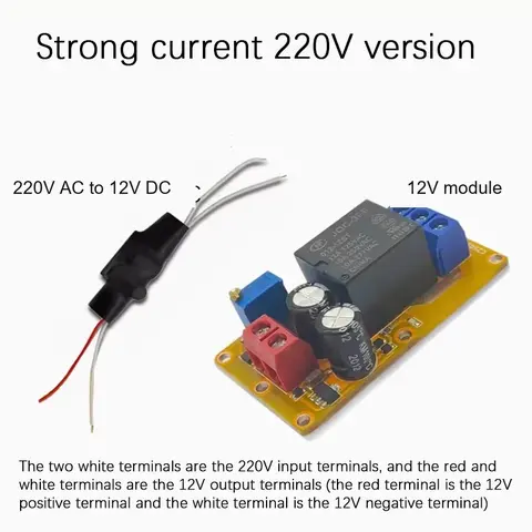
B2J0101 Economical Power-up Delay Module
Low-cost power-up delay relay module with a 2-30 second adjustable delay and no trigger input required.
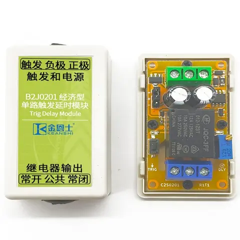
B2J0201 Economical Trigger Delay Module
Level-triggered delay relay module with jumper-selectable high/low trigger and a 2-30s adjustable delay.
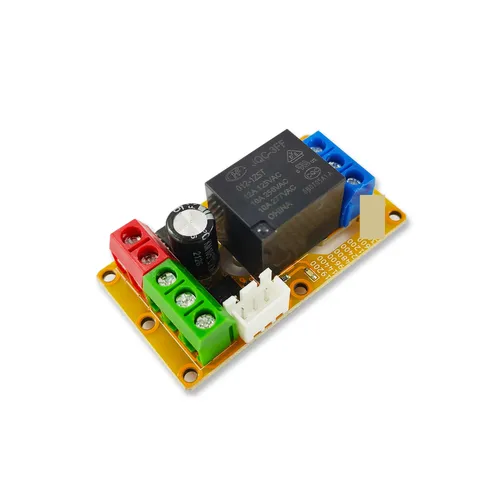
B2J0302 Enhanced Single MODBUS-485 I/O Module
Enhanced single-channel MODBUS-RTU/RS-485 I/O module: 1 digital input, 2 analog inputs, 1 relay or transistor output, AT command support and a 5V sensor supply — the successor to the discontinued B2J0301.