
B2J0201 Economical Trigger Delay Module
Level-triggered delay relay module with jumper-selectable high/low trigger and a 2-30s adjustable delay.
 🔍 Click to enlarge · 1/6
Technical Specifications
| Delay mode | Level-triggered delay (starts on an external trigger signal, not at power-up) |
|---|---|
| Trigger method | High-level trigger (>2V) or low-level trigger (short to ground), selected by a three-pin header and jumper cap; an on-board trigger button can also start the delay |
| Delay range | 2 - 30 seconds, adjustable via on-board potentiometer (clockwise to increase, counterclockwise to decrease) |
| Core chip | NE555 |
| Output | Single-channel relay, NO/NC (open-drain transistor output type also available) |
| Supply voltage (rated) | 5V / 9V / 12V / 18V / 24V DC |
| Supply voltage (normal operating range) | 5V DC: 4.8-5.2V; 9V DC: 8.5-11V; 12V DC: 11-14V; 18V DC: 16-20V; 24V DC: 20-28V |
| Power supply ripple | < 1 Vp-p |
| Supply current | < 50 mA (typically 40 mA when the relay is made) |
| Trigger input stress (normal) | High-level selected: DC 0-30V; Low-level selected: DC 0-5V |
| Output stress (normal) | Relay type: DC 30V or AC 0-220V, 8A; Transistor type: DC 12-48V, 8A |
| Output isolation voltage (normal) | Relay type: < 250V; Transistor type: < 130V |
| Operating temperature | -20 to 60 degrees C |
| Absolute max supply voltage | 5V: 5.3V; 9V: 11.5V; 12V: 15V; 18V: 22V; 24V: 30V DC |
| Self-resettable fuse | DC 30V, 500mA |
| Absolute max trigger input stress | DC 50V |
| Absolute max output stress | Relay type: AC 250V, 10A; Transistor type: DC 55V, 10A |
| Absolute max output isolation voltage | Relay type: DC 1000V, 60s (type test only); Transistor type: DC 250V, 60s (type test only) |
| Relay mechanical life | > 100,000 operations (> 10,000 under heavy load) |
| Storage temperature | -40 to 85 degrees C |
| Electrostatic discharge resistance | IEC 61000-4-2: 1kV on all terminals, module functions normally; 2kV, module not permanently damaged |
| Electrical fast transient resistance | IEC 61000-4-4: 500V/5kHz/2min on all terminals, module functions normally (delay time may slightly change); 1kV, module not permanently damaged |
| Surge resistance | IEC 61000-4-5: 1kV to ground on power terminals, module not permanently damaged (guaranteed by design) |
| Creepage distance | > 9.2mm from relay terminal to logic side (requirement > 6mm), pollution degree 3, material category IIIa/IIIb |
| Electrical clearance | > 2.2mm from relay terminal to logic side (requirement > 2mm) |
| PCB dimensions | 55mm (L) x 30mm (W), tolerance +/-5% |
| Mounting hole spacing | 49mm (top-bottom) x 24.5mm (left-right) |
| Terminal spacing | 5.08mm |
Overview
The B2J0201 is an economical, level-triggered delay relay module for control circuits that must act on an external signal rather than on power-up. Unlike a plain power-on delay module, it carries a dedicated trigger input: after power-up the relay stays open, and it only makes once an external voltage-level signal (or the on-board trigger button) is applied, making it suited to "signal detected -> relay makes -> signal removed -> delayed release" control logic.
It is available in 5V, 9V, 12V, 18V or 24V DC supply versions (M31, 12V DC with relay output, ships by default), with trigger polarity set by a three-pin header and jumper cap for either high-level (>2V) or low-level (short to ground) triggering. Delay time is adjustable from 2 to 30 seconds on an on-board potentiometer, and the single-channel relay output is rated 250V AC / 10A (NO/NC), with an open-drain transistor output version also available for 12-48V DC / 10A inductive loads.
Features & Benefits
The Relay Waits for a Signal, Not for Power
Terminal 0 is a dedicated trigger input with voltage-threshold detection, so the relay stays open at power-up and no countdown runs until a real signal arrives. That removes the nuisance pulse a power-on delay module gives you every time the panel is switched on, and it means the module can sit permanently powered and armed, reacting only when the sensor speaks.
High or Low Trigger Chosen by Moving One Jumper Cap
Move the cap between "o" and "+" and any positive voltage above 2V at terminal 0 starts the sequence; move it to "o" and "-" and a simple short to ground does the job. One part number therefore accepts a PNP sensor, an NPN sensor, a PLC output, a dry contact or a push button - no rewiring of the field side and no second SKU to stock.
Signal Holds the Relay, Release Starts the Delay
A momentary pulse closes the relay for the set time T; a signal that stays present keeps the relay closed for as long as it lasts and only then times out T before releasing. This is exactly the "stay on while something is there, switch off a while after it leaves" logic that lighting, fans and alarms need, and it comes free in the hardware instead of costing you two PLC rungs and a timer block.
NE555 Timing Core with a Screwdriver-Set 2-30 s Delay
An analogue NE555 core and an on-board potentiometer cover 2 to 30 seconds - clockwise longer, counterclockwise shorter. Setting the delay takes a screwdriver and ten seconds on site: no software, no programming cable, no host computer, and nothing to re-flash if a technician wants 20 s instead of 8 s. The trigger button (No. 6) lets the installer prove the setting on the spot without a signal source.
One Board, Five Supply Voltages, 40 mA Typical
5V, 9V, 12V, 18V or 24V DC versions are selected by the first digit of the [dd] ordering field (M31 = 12V relay output ships by default), with defined windows such as 11-14V for the 12V type and 20-28V for the 24V type. Draw is under 50 mA (typically 40 mA with the relay energised), so the module usually runs off the sensor's own supply rather than needing a dedicated one. Custom supply voltages are available.
Isolated Dry Contact That Switches Mains-Level Loads
The single-channel relay gives both NO and NC contacts rated AC 250V / 10A absolute maximum (AC 0-220V or DC 30V at 8A in normal working conditions), fully isolated from the low-voltage logic - up to DC 1000V for 60s on type test. A 5V sensor circuit can therefore switch a 220V corridor lamp directly, with mechanical life above 100,000 operations.
Details That Show Up Only When Something Goes Wrong
Reverse-polarity and overcurrent protection plus a DC 30V / 500 mA self-resetting fuse cover the wiring mistakes that kill cheap modules. The PCB carries a routed creepage slot measuring over 9.2 mm against the 6 mm requirement (clearance over 2.2 mm against 2 mm) at pollution degree 3, and the trigger input survives DC 50V absolute maximum - so a 24V line accidentally landed on a trigger terminal does not end the job.
Transistor Output Option for Silent, High-Cycle DC Switching
Order the transistor version (second [dd] digit = 2) for an open-drain output rated 12-48V DC / 10A with a built-in 10A freewheeling diode that drives inductive loads such as solenoids and motors directly - no contact wear, no click, no arc. Because the NE555 state can become invalid at power-down and pulse the transistor for around 100 ms, power the module up before the output and down after it.
Applications
Models & Ordering Information
B2J0201 Ordering Code
PDF & 3D CAD Downloads
Browse all downloadsB2J0201 Economical Trigger Delay Module User Manual
Confirm the document and CAD file match the exact ordered version before installation or mechanical design. Contact us if your model is not listed.
How to Select
- Bare-board supply, enclosure and DIN-rail mounting are ordering options for this B2J/E4J module. Specify what is included on the quotation; do not assume an enclosure or mounting kit is supplied as standard.
- Choose B2J0201 (level-triggered delay) when the action must be started by an external level signal or button and the trigger polarity needs to be selectable.
- If no trigger signal is needed and the output should switch on automatically at power-up, choose the simpler, lower-cost B2J0101 (power-on delay) instead.
- If the application needs multiple delay modes, long second/minute/hour delays, high precision, or voltage-threshold sensing, choose the full-featured B2J0601 (universal multi-mode delay) instead.
- Use high-level trigger mode for sensors that output a positive voltage above 2V on detection.
- Use low-level trigger mode for switches or sensors that pull the trigger terminal to ground on detection.
- Select the M31 default (12V DC, relay output) for mains-adapter-powered 220V AC installations such as sound-activated lighting.
- Select the transistor output version for frequent triggering or silent switching of 12-48V DC inductive loads, and add power sequencing (module powered up first, then output; output powered down first, then module) since the transistor type can briefly conduct at power-off.
- This module is a general-purpose commercial-grade delay relay, not a forcibly-guided safety relay; for strong-interference industrial environments add power/port filters or use an EFT-resistant supply with a cord shorter than 3m.
📘 Need the full method? NPN vs PNP Sensor Outputs Explained
When NOT to specify the B2J0201 — and what to use instead
You want the delay to start automatically at power-up with no external signal
Why not: B2J0201 needs an external trigger or a button press before anything happens. The relay stays open and no countdown runs on power alone.
Use instead: B2J0101, which is a power-up delay and needs no trigger input.
You need edge triggering, cyclic on/off patterns, self-locking behaviour, or minute / hour ranges
Why not: B2J0201 offers one trigger topology only — level trigger, hold then release, on a 2-30 second potentiometer. There are no edge, cyclic or self-locking modes and no time unit beyond seconds.
Use instead: B2J0601, whose 26 modes cover high/low level, rising/falling edge, cyclic and self-locking behaviour across second, minute and hour ranges.
Wiring a 12 V or 24 V level signal into the low-level trigger path
Why not: In low-level trigger mode the trigger input's normal operating stress is DC 0-5 V. The DC 50 V figure is the absolute maximum, not a working level.
Use instead: Use high-level trigger mode instead (rated DC 0-30 V normal), or B2J0601, whose trigger input doubles as a 0-30 V adjustable threshold detector.
Deploying where motors or contactors share the supply
Why not: B2J0201 is tested to IEC 61000-6-1 light-industry levels (500 V EFT), not the 1 kV EFT of IEC 61000-6-2.
Use instead: Add power and port filtering or an EFT-resistant supply with a cord under 3 m, or move to E4J0101, measured at 2 kV EFT.
A safety interlock, emergency-stop or guard-release delay
Why not: Its own selection guide describes it as a general-purpose commercial-grade delay relay, not a forcibly-guided safety relay. It carries no Type / SIL / PL rating.
Use instead: DA31 Emergency-Stop Safety Relay Module or DQSRN Safety Relay Module.
You need to monitor the trigger event or delay status remotely
Why not: B2J0201 has no communication port of any kind. Status is two on-board LEDs; settings are local only, by jumper and potentiometer.
Use instead: B2J0302 for a networked MODBUS point, or E4J0101, which adds TTL / USB connectivity.
Specifications we do not publish yet
We only publish a figure once we are confident it is true. The items below are still being validated through further testing and real-world customer feedback, so for now we would rather leave them open than guess. If one of them matters to your design, ask us for the latest validated status.
- Electrical (load-switching) contact life under the rated 8 A load, as distinct from the published mechanical life.
- Relay brand and model number.
- Ingress protection (IP) rating.
- MTBF.
- Quantified temperature drift of the delay circuit. The manual notes EFT exposure may shift the delay slightly but gives no figure.
- Operating and storage relative humidity range.
- Terminal wire gauge and screw torque.
- Certification status — the manual states none. Certification documents are available on request.
Frequently Asked Questions
What supply voltages does the B2J0201 trigger delay module support?
How is the delay time adjusted and what is the range?
How do I configure high-level versus low-level triggering?
What happens if the trigger signal is still present when the delay would normally end?
What is the difference between the relay output and transistor output versions?
Does the B2J0201 carry industrial safety or compliance certification?
Related Categories and Example Products
Explore other functions that may be needed in a machine or line. The products below are category examples, not pre-validated electrical or safety combinations. Confirm each interface and application separately: Proximity Sensors · Photoelectric Sensors · Laser Distance Sensors
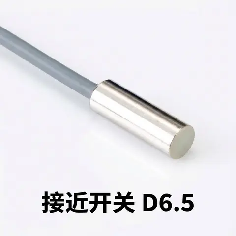
D6.5 Series Inductive Proximity Sensors (Ultra-Short 18mm / Y-Type / 35mm / 45mm)
6.5mm-diameter inductive proximity sensors for tight-clearance mounting where M8 sensors won't fit.
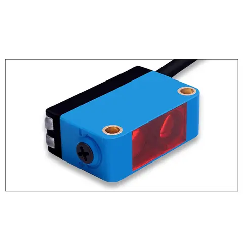
BGS-CX441 / BGS-CX442 Background Suppression Photoelectric Sensor
Wire-adjustable BGS sensor with 2 mm or 15 mm spot, 10-300 mm range, published black/white differential distance.
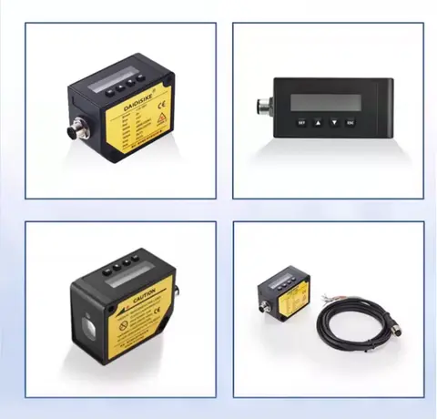
DDA-Y & DDB-Y Industrial Laser Distance Sensor (Phase-Shift)
Phase-shift laser distance sensors: 0.2-100 m range, millimeter accuracy, RS485 Modbus RTU, switching or analog output.
Related Products in Relay & Timer Modules
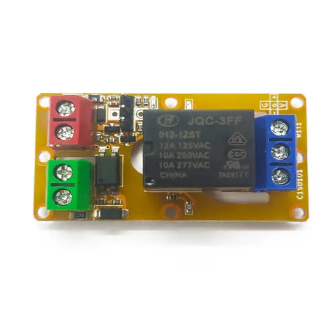
A1J0101 Economical Input Amplifier Module
Optocoupler-isolated input amplifier that turns a low-voltage signal into a 250V AC / 10A relay output.
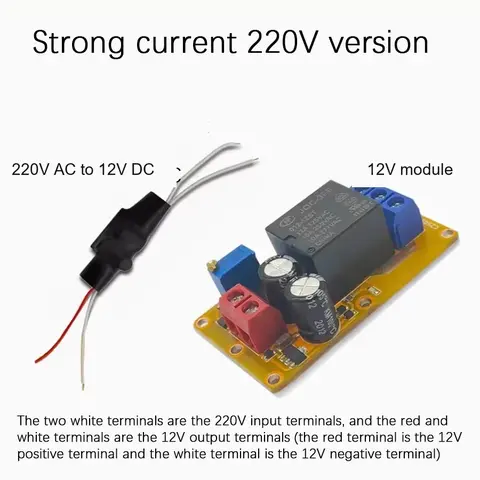
B2J0101 Economical Power-up Delay Module
Low-cost power-up delay relay module with a 2-30 second adjustable delay and no trigger input required.
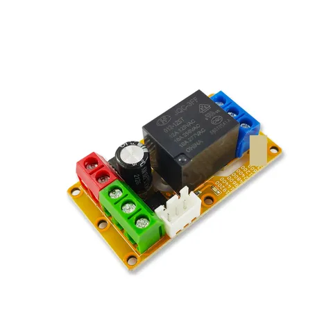
B2J0302 Enhanced Single MODBUS-485 I/O Module
Enhanced single-channel MODBUS-RTU/RS-485 I/O module: 1 digital input, 2 analog inputs, 1 relay or transistor output, AT command support and a 5V sensor supply — the successor to the discontinued B2J0301.
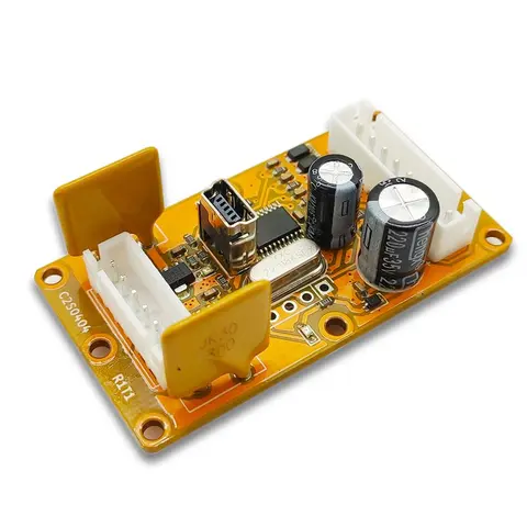
B2J0401 MODBUS Analog/Digital I/O Module
Economical MODBUS-RTU/RS-485 module: 4 analog/digital inputs plus 2 MOSFET PWM/PTO outputs.