
B2J0302 Enhanced Single MODBUS-485 I/O Module
Enhanced single-channel MODBUS-RTU/RS-485 I/O module: 1 digital input, 2 analog inputs, 1 relay or transistor output, AT command support and a 5V sensor supply — the successor to the discontinued B2J0301.
▶ Watch it in action: B2J0302 MODBUS RS-485 Relay I/O Module — Wiring & PC Control Demo (MODBUS-RTU)
 🔍 Click to enlarge · 1/6
Technical Specifications
| Product Type | Enhanced economical single-channel MODBUS-RTU RS-485 I/O module (successor to B2J0301) |
|---|---|
| Digital Input | 1 channel (DIN0), high-sensitivity; rated 0-30 V working, 50 V absolute maximum |
| Input Threshold | Adjustable in 1 mV steps via THRES register (stored permanently); approx. 1 V default |
| Analog Input AIN0 | 0-35 V range, shares the digital input terminal, with industrial protection circuit |
| Analog Input AIN1 | 0-5 V range on auxiliary connector (no protection — observe the range) |
| Analog Resolution | 1 mV per register LSB (16-bit register); about 10 bits effective, typical accuracy 3% of full scale |
| Sensor Supply | 5 V / 20 mA max on auxiliary connector for small sensor modules |
| Output (Relay Version) | 1 relay, NO + NC contacts; 30 V DC or 0-220 V AC at 8 A working; 250 V AC / 10 A absolute maximum |
| Output (Transistor Version) | 1 open-drain channel, 12-48 V DC at 8 A working (55 V / 10 A absolute maximum), built-in 10 A freewheel diode |
| Relay Mechanical Life | Over 100,000 operations (over 10,000 at heavy load) |
| Output Isolation | Relay version: working isolation under 250 V (1000 V DC / 60 s type test); transistor version: under 130 V (250 V DC type test) |
| PWM (Transistor Version Only) | 86400 Hz base with divider 1-256 (approx. 337 Hz - 86.4 kHz); duty 0-256 steps, 8-bit effective |
| Communication | RS-485 half-duplex; MODBUS-RTU and ASCII AT-command protocol simultaneously |
| MODBUS Address | 1-247, configurable over the bus; factory default 0x02 |
| Serial Defaults | 9600 baud, 8 data bits, even parity, 1 stop bit; push-button restores defaults; board-marked presets 300-19200 baud |
| Product ID Code | 0x2302 (readable over MODBUS for automatic identification) |
| Jog Delay | 10 ms units via DELAY register; module stays MODBUS-responsive during delay and the delay can be cancelled from the bus |
| Trigger Delay | 16 edge/level-triggered modes; delay value 0-1023 in units of 10 ms / 1 s / 1 min / 1 h |
| Input Counter | 16-bit rising-edge counter, up to 5 Hz, clearable over the bus |
| Input Filter | Configurable 1-65535 ms de-bounce / anti-interference filter |
| AT Auto-Report | On input change (1-100 repeats) or periodic from every 100 ms to every 1 min |
| Supply Versions | 5 V (4.8-5.2), 9 V (8.5-11), 12 V (11-14), 24 V (20-28) DC; custom voltages for batch orders |
| Supply Current / Ripple | Under 50 mA (approx. 40 mA typical with relay energised); ripple under 1 V peak-peak |
| Protection | Reverse-polarity, 500 mA resettable fuse, ESD / EFT / surge per IEC 61000-6-1:2016 light-industrial levels |
| Insulation Coordination | Creepage over 9.2 mm and clearance over 2.2 mm from relay side to logic side, pollution degree 3, basic insulation |
| Operating / Storage Temperature | -20 to +60 C operating; -40 to +85 C storage |
| Dimensions | PCB 55 x 30 mm, mounting holes 49 / 24.5 mm, terminal pitch 5.08 mm; enclosure version 60.5 x 35.5 x 22 mm |
| Interface Hardware | 8 screw terminals, 1 reset button, power LED (green) and action LED (blue); auxiliary connector on analog version |
Overview
The B2J0302 is an enhanced economical single-channel MODBUS-RTU RS-485 I/O module built around a dedicated control IC. One high-sensitivity digital input, one isolated relay output (NO and NC contacts, up to 250 V AC / 10 A absolute maximum) and a half-duplex RS-485 port make it a complete networked switch point for PLC, SCADA, IoT-gateway and distributed-control installations. Supply versions for 5, 9, 12 and 24 V DC are available from stock, and every serial parameter — address 1-247, baud rate, parity, stop bits — can be set over the bus, with a push-button restore to the factory default of address 0x02, 9600 baud, 8 data bits, even parity, 1 stop bit.
What makes the B2J0302 the enhanced model in the series is everything layered on top of that basic switch point. It adds two analog voltage inputs — a 0-35 V channel with industrial protection circuitry shared with the digital input terminal, and a separate 0-5 V channel on an auxiliary connector that also provides a 5 V / 20 mA supply for small sensor modules — read over MODBUS with 1 mV register resolution. It adds an adjustable digital-input threshold, a pulse counter, a configurable 1-65535 ms input filter, a trigger-delay engine with sixteen edge- and level-triggered modes from 10 ms up to 1023 hours, and an ASCII AT-command protocol that works alongside MODBUS-RTU for quick scripted control and automatic input reporting. On the transistor-output variant it also provides a PWM output from roughly 337 Hz to 86.4 kHz for simple motor-drive and dimming applications.
The B2J0302 directly replaces the discontinued B2J0301. It is wiring-compatible and protocol-compatible — same terminal layout, same 55 x 30 mm board, same MODBUS commands for the input and the relay — so existing installations can swap boards without rewiring. Unlike the B2J0301, it keeps responding to MODBUS commands even while a jog delay is running, and a delay in progress can be cancelled over the bus. If you are holding B2J0301 drawings or order codes, order the B2J0302 and your documentation still applies; the extra functions are additive.
Features & Benefits
Drop-In Successor to the B2J0301
Same terminal layout, same 55 x 30 mm board, same MODBUS commands for reading the input and driving the relay. Existing B2J0301 installations swap over without rewiring or host-software changes — the enhancements are all additive.
Two Analog Inputs Plus a Sensor Supply
A 0-35 V protected channel and a 0-5 V auxiliary channel are read over MODBUS with 1 mV register resolution, and the auxiliary connector provides 5 V / 20 mA to power a small sensor head — a battery-voltage or sensor-signal monitor and a remote switch in one node.
One Networked Switch Point, Fully Isolated
The relay gives you clean NO and NC contacts rated to 220 V AC / 8 A working (250 V AC / 10 A absolute maximum) with over 100,000-operation mechanical life — control a contactor, valve, lamp or heater from any MODBUS master over two RS-485 wires.
AT Commands Alongside MODBUS-RTU
Simple ASCII commands (AT+SET, AT+CLR, AT+PIN?, AT+ADC?) work without CRC calculation — ideal for quick bring-up, scripted test rigs and lightweight controllers. The module tells MODBUS and AT frames apart automatically, and can push input states on change or on a fixed schedule.
Delay Logic That Stays Reachable
Jog delay in 10 ms units plus a 16-mode trigger-delay engine covering 10 ms to over 1000 hours. Unlike the previous generation, the module keeps answering MODBUS during a delay, and a running delay can be cancelled from the bus.
PWM on the Transistor Variant
The open-drain version adds a PWM channel adjustable from about 337 Hz to 86.4 kHz with 8-bit duty resolution — enough for LED dimming, small DC motor speed control and proportional valve drive from the same MODBUS node.
Protected Like an Industrial Device
Reverse-polarity protection, a 500 mA resettable fuse, and ESD / EFT / surge immunity verified to IEC 61000-6-1:2016 light-industrial levels. Creepage from the relay side to the logic side exceeds 9.2 mm at pollution degree 3.
Every Serial Parameter Configurable
Address 1-247, all common baud rates, parity and stop bits are set over the bus and stored permanently. A push-button restores the factory default (address 0x02, 9600, 8E1) if a module ever arrives at your bench with unknown settings.
Applications
Models & Ordering Information
B2J0302 Series — enhanced single-channel MODBUS-485 I/O
How to Select
- Bare-board supply, enclosure and DIN-rail mounting are ordering options for this B2J/E4J module. Specify what is included on the quotation; do not assume an enclosure or mounting kit is supplied as standard.
- Start from the output your load needs. Relay versions (M-1 codes) give volt-free NO/NC contacts for AC loads, contactors and mixed-voltage circuits up to 220 V AC / 8 A working. Transistor versions (M-2 codes) switch 12-48 V DC loads up to 8 A and add the PWM channel — choose them for motors, LED strips and fast-cycling DC loads that would wear a relay out.
- Pick the supply-voltage digit to match the rail you already have in the cabinet: M1x = 5 V, M2x = 9 V, M3x = 12 V (default), M4x = 24 V. The module draws under 50 mA, so it can share almost any existing control-power supply.
- If you are replacing a discontinued B2J0301, order the same M[dd] suffix you used before — wiring, board size and MODBUS commands carry over unchanged, and the analog inputs and AT protocol are simply available when you want them.
- Use AIN0 (0-35 V, protected) for supply rails, battery voltages and rough industrial signals; reserve AIN1 (0-5 V, unprotected) for clean sensor outputs powered from the module's own 5 V / 20 mA supply. Do not exceed 5 V on AIN1.
- Bare-board modules are recommended for safe extra-low voltage (up to 36 V) control only. If the relay will switch mains voltage, specify the enclosure version and keep the mandated clearances on your mounting plate.
- For counting, de-bounce or trigger-delay duties, check the limits before committing: the counter accepts up to 5 Hz, the filter spans 1-65535 ms, and trigger delays run from 10 ms to 1023 hours in four unit ranges — inside those bounds no external timer or PLC is needed.
- Plan the bus like any RS-485 network: up to standard loading per segment, addresses 1-247, and one twisted pair daisy-chained through all modules. Every B2J0302 answers the product-ID register, so hosts can auto-discover what is installed.
- If you need more than one channel per node, step up to the D3J series: D3J01xx for multi-channel inputs, D3J02xx for multi-channel outputs, D3J03xx for mixed I/O on one board — the B2J0302 is the right choice only when one input and one output per location is the plan.
📘 Need the full method? NPN vs PNP Sensor Outputs Explained
When NOT to specify the B2J0302 — and what to use instead
You need many I/O channels at one location
Why not: The B2J0302 is deliberately a single-point node: one digital input, one output. Wiring several of them side by side costs more per channel than one multi-channel module.
Use instead: D3J0104/D3J0108/D3J0116/D3J0128 for 4-28 inputs, D3J0202-D3J0214 for 2-14 outputs, or D3J03xx for mixed I/O on one board.
The output is part of a safety function (emergency stop, light curtain, guard door)
Why not: The B2J0302 is a standard I/O module with no safety rating, no forcibly guided contacts and no redundant architecture — it must never be the device that makes a machine safe.
Use instead: DQSRN or DA31 safety relay modules with forcibly guided contacts, wired per your risk assessment.
You want local timing logic set by knobs, with no bus at all
Why not: Every configuration on the B2J0302 is done over RS-485; there are no potentiometers or DIP switches for field staff to adjust without a host.
Use instead: B2J0201 for a simple local trigger-delay relay, or E4J0101 with panel controls and TTL/USB connectivity.
You only need a bare delay relay and cost is everything
Why not: If the analog inputs, AT protocol and trigger engine will never be used, the enhanced module is more capability than the job needs.
Use instead: B2J0101 (power-up delay) or B2J0201 (trigger delay) — simpler boards at a lower price point.
The load needs high-resolution or high-frequency PWM
Why not: PWM on the transistor variant is 8-bit and tops out at 86.4 kHz with frequency set by integer dividers — fine for dimming and small motors, not for servo drives or Class-D audio-grade control.
Use instead: A dedicated motor driver or servo amplifier, with the B2J0302 handling enable/direction signalling if needed.
Bare board switching mains voltage in an open cabinet
Why not: Without the enclosure, the module is recommended for safe extra-low voltage (0-36 V) control only; exposed mains on an open PCB is an electric-shock hazard and violates the intended use.
Use instead: The enclosure version of the B2J0302, or a DIN-rail terminal-block output module such as the D3J0202 family.
B2J0302 vs the discontinued B2J0301 — what the upgrade adds
The B2J0301 has been discontinued and the B2J0302 is its direct successor. Wiring, board size, supply options and the basic MODBUS commands are identical, so it is a drop-in replacement — the rows below show what you gain.
| Feature | B2J0301 (discontinued) | B2J0302 (current) |
|---|---|---|
| Status | Discontinued — no longer orderable | In production, direct replacement |
| Digital input | 1, fixed approx. 1 V threshold | 1, threshold adjustable in 1 mV steps |
| Analog inputs | None | 2 (0-35 V protected + 0-5 V auxiliary), 1 mV resolution |
| Sensor power supply | None | 5 V / 20 mA on auxiliary connector |
| Relay / transistor output | 1, up to 250 V AC / 10 A abs. max | Same rating, unchanged wiring |
| MODBUS during jog delay | Not responsive until delay ends | Fully responsive; delay can be cancelled over the bus |
| Trigger-delay engine | Not available | 16 edge/level modes, 10 ms to 1023 h |
| Input counter / filter | Not available | 16-bit counter (to 5 Hz); 1-65535 ms filter |
| AT command protocol | Not available | Yes, alongside MODBUS-RTU, with auto-reporting |
| PWM output | Not available | On transistor variant: approx. 337 Hz - 86.4 kHz, 8-bit duty |
| Board size / mounting | 55 x 30 mm, 49 / 24.5 mm holes | Identical |
| Serial defaults & reset button | 0x02, 9600, 8E1 | Identical |
Compiled from the B2J0302 technical reference manual (R1T1) and the retired B2J0301 documentation.
Specifications we do not publish yet
We only publish a figure once we are confident it is true. The items below are still being validated through further testing and real-world customer feedback, so for now we would rather leave them open than guess. If one of them matters to your design, ask us for the latest validated status.
- Baud rates above the board-marked 19200 preset list — higher rates are still being validated, so ask us before designing a faster bus around this module
- Analog-input accuracy drift over the full -20 to +60 C temperature range is not published; the 3% typical figure is at room temperature
- IP rating of the enclosure version is not published — treat it as indoor, non-washdown until we confirm a figure
- MTBF / service-life figures for continuous 24-7 operation are not published yet
- Module weight (bare board and enclosure versions) is not published
- Formal CE documentation status — EMC performance is verified to IEC 61000-6-1:2016 levels as listed in the specifications; certificate documents are available on request once issued
- The 18 V supply option mentioned alongside 5/9/12/24 V in early material is not in the current ordering table — ask us to confirm availability before ordering
- Maximum RS-485 cable length validated at each baud rate is not published; standard RS-485 practice applies
Frequently Asked Questions
Is the B2J0302 a drop-in replacement for the B2J0301?
What is the difference between the relay and transistor output versions?
How do I read the two analog inputs?
Can AT commands and MODBUS-RTU really be used at the same time?
What are the factory communication settings, and what if I lose track of a module's configuration?
Can the B2J0302 switch mains voltage?
How does the jog delay work, and how is the trigger-delay engine different?
How many modules can share one RS-485 bus?
Related Categories and Example Products
Explore other functions that may be needed in a machine or line. The products below are category examples, not pre-validated electrical or safety combinations. Confirm each interface and application separately: Proximity Sensors · Photoelectric Sensors · Laser Distance Sensors

D6.5 Series Inductive Proximity Sensors (Ultra-Short 18mm / Y-Type / 35mm / 45mm)
6.5mm-diameter inductive proximity sensors for tight-clearance mounting where M8 sensors won't fit.
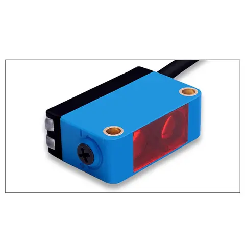
BGS-CX441 / BGS-CX442 Background Suppression Photoelectric Sensor
Wire-adjustable BGS sensor with 2 mm or 15 mm spot, 10-300 mm range, published black/white differential distance.
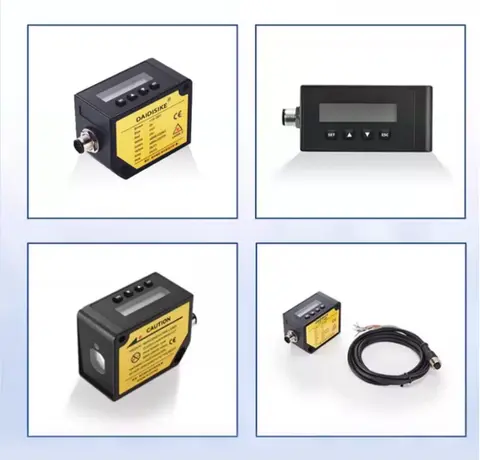
DDA-Y & DDB-Y Industrial Laser Distance Sensor (Phase-Shift)
Phase-shift laser distance sensors: 0.2-100 m range, millimeter accuracy, RS485 Modbus RTU, switching or analog output.
Related Products in Relay & Timer Modules
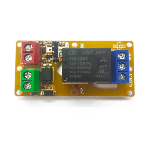
A1J0101 Economical Input Amplifier Module
Optocoupler-isolated input amplifier that turns a low-voltage signal into a 250V AC / 10A relay output.
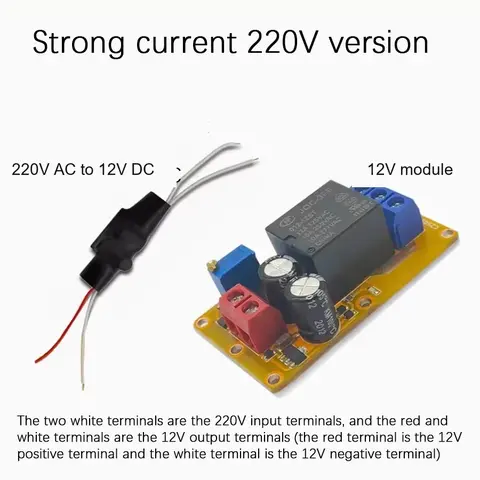
B2J0101 Economical Power-up Delay Module
Low-cost power-up delay relay module with a 2-30 second adjustable delay and no trigger input required.
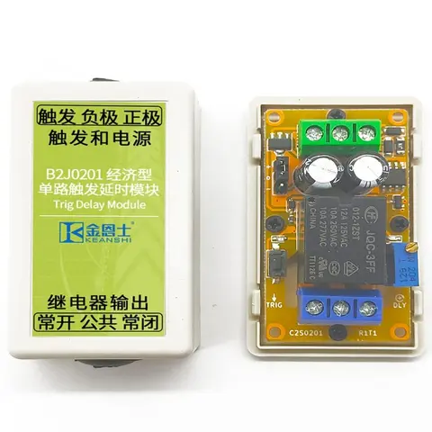
B2J0201 Economical Trigger Delay Module
Level-triggered delay relay module with jumper-selectable high/low trigger and a 2-30s adjustable delay.
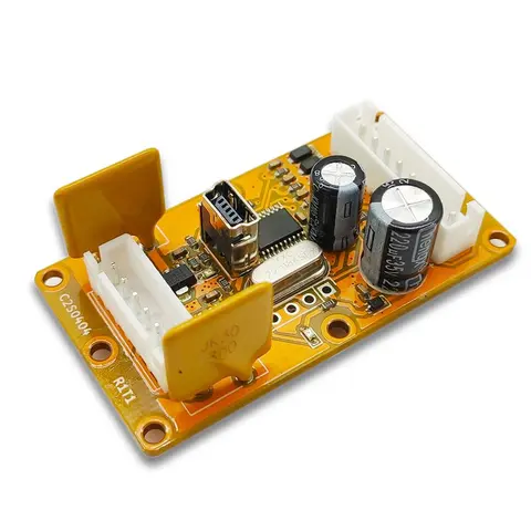
B2J0401 MODBUS Analog/Digital I/O Module
Economical MODBUS-RTU/RS-485 module: 4 analog/digital inputs plus 2 MOSFET PWM/PTO outputs.