
D3J0116 Modbus
16-channel fully isolated Modbus-RTU/RS-485 digital input module for centralized cabinet and line signal acquisition.
 🔍 Click to enlarge · 1/3
Technical Specifications
| Order Code | D3J0116 (default no wireless, RS-485 only) |
|---|---|
| Product ID / Default Slave Address | 0x3116 |
| Inputs | 16-channel fully isolated digital input (plus 2 analog inputs, 1 x 5V/100mA power output) |
| Outputs | None (pure input type, no relay/transistor output) |
| Communication Interface | RS-485 (Modbus-RTU, default 9600/8-Even-1); optional 2.4GHz wireless |
| Supply Voltage | DC 11-28V |
| Physical Interface | RS-485 half-duplex, differential twisted pair A/B; plus USB port; optional 2.4GHz wireless Modbus-OTA |
| Communication Protocol | Modbus-RTU (primary); plus Modbus-ASCII, AT commands; wireless Modbus-OTA |
| Default Baud Rate | 9600 bps |
| Default Data Format | 8 data bits, even parity, 1 stop bit |
| Default Slave Address | 0x02 |
| Optional Baud Rates | 300 / 600 / 1200 / 1800 / 2400 / 4800 / 7200 / 9600 / 14400 / 19200 / 28800 / 38400 / 56000 / 57600 / 76800 / 115200 bps |
| Optional Parity | None / Odd / Even (default Even) |
| Optional Stop Bits | 1 (default) / 1.5 / 2 |
| Slave Address Range | 1-247 (0x01-0xF7) |
| USB Mode Address | Fixed at 0x01 when USB is connected; RS-485 then switches to master mode |
| Input Threshold | Approx. 3V |
| Input Counting | Per-channel DINnCNT, increments on rising edge; pulse frequency up to 5Hz, rolls over at 65535, clearable by write |
| Input Filtering | Per-channel DINnFLT, 1-65535ms adjustable (0=off), savable through power loss via MODESAVE="MS" |
| Supported Function Codes | 0x02 Read Discrete Inputs, 0x04 Read Input Registers, 0x03 Read Holding Registers, 0x06 Write Single Holding Register, 0x10 Write Multiple Holding Registers, 0x16 Mask Write, 0x17 Read/Write Multiple Holding Registers, 0x11 Report Device ID |
| Exception Codes | 0x01 ENOFUNC (unsupported function), 0x02 ENOADR (address/quantity out of range), 0x03 EINVAL (invalid length/field), 0x04 EDEVICE (execution error) |
| Supply Ripple | < 1Vp-p |
| Supply Current | < 1500mA |
| Communication Port Stress | DC 0-5V |
| Input Port Stress | DC 0-30V |
| Communication Isolation Voltage | < 250V |
| Input Isolation Voltage | < 250V |
| Operating Temperature | -20 to 60C |
| Max Supply Voltage (absolute) | DC 28V |
| One-Time Fuse | DC 250V, 3000mA, slow-blow |
| Max Communication Port Stress (absolute) | DC 50V |
| Max Input Port Stress (absolute) | DC 50V |
| Max Communication Isolation Voltage (absolute) | DC 1000V, 60 seconds (type test only) |
| Max Input Isolation Voltage (absolute) | DC 1000V, 60 seconds (type test only) |
| Storage Temperature | -40 to 85C |
| ESD Immunity | 4kV to all terminals -> normal operation (Criterion A) |
| EFT Immunity | 2kV/5kHz/2min -> normal (A); 4kV/5kHz/2min -> no permanent damage (C) |
| Surge Immunity | 1kV, all terminals to ground -> no permanent damage (C) |
| Creepage Distance | > 6.5mm measured (requirement > 6mm, pollution degree 3) |
| Clearance | > 2.2mm measured (requirement > 2mm, pollution degree 3) |
| Input Response Time | Typical 20ms |
| Serial Command Reply Time | Max 25ms |
| Module Dimensions (L x W x H) | 107 x 88 x 59mm (tolerance +/-5%) |
| Terminal Pitch | 5.08mm |
| Model Coding | D3J01[aa]R[b]T[c]M[d]: aa = input channels (04/08/16/28); b/c = major/minor version; d 1st digit = wireless option (1 = no wireless, RS-485 only, default; 2 = 2.4GHz wireless available) |
Overview
The D3J0116 is a 16-channel fully isolated digital input module built around a dedicated ASIC and communicating over RS-485 using the Modbus-RTU protocol. It is a pure input device with no relay or transistor outputs, designed for panel builders and integrators who need to bring a dozen or more switch, limit, or status signals from a mid-size control cabinet or a production line section onto a single Modbus node.
The module reads all 16 channels over RS-485 at a default of 9600 bps, 8 data bits, even parity, 1 stop bit, and slave address 0x02, with a supported address range of 1-247. It also includes a USB port for configuration and USB-to-serial operation, per-channel edge counting up to 5Hz and adjustable input filtering from 1 to 65535ms, plus 2 auxiliary analog input channels and a 5V/100mA sensor power output.
Features & Benefits
Sixteen Field Points, One Bus Node
When a dozen or more switch signals already sit in one cabinet, this module takes all 16 on a single slave address instead of two or three smaller modules on two or three addresses. Master polling stays simple, SCADA tag mapping stays short, and the enclosure, power feed, and communication circuit cost is spread across 16 channels rather than 4 or 8 - so the cost per acquired point drops and there are fewer spare part numbers to stock.
Every Input Isolated, 2kV EFT Survived
All 16 digital inputs and the RS-485 port are electrically isolated from internal logic (isolation voltage below 250V, type-tested to DC 1000V for 60 seconds). EFT immunity is 2kV/5kHz with normal operation - double the 1kV that IEC61000-6-2-2016 asks of industrial equipment - and 4kV causes no permanent damage. That is the margin that keeps a densely wired cabinet full of contactors from corrupting your status data.
Debouncing Happens in Hardware, on Every Channel
Each of the 16 channels carries its own DINnFLT filter, adjustable from 1 to 65535ms (0 disables it) and savable through power loss with MODESAVE. A worn limit switch that chatters gets a 50ms filter; a clean proximity sensor gets none. No debounce timers to write in the PLC, no scan time burned on 16 channels of software filtering.
Counting Built In, No PLC Logic Required
Every channel also has its own DINnCNT rising-edge counter that tracks pulses up to 5Hz, rolls over at 65535, and clears when you write to it. Cycle counts, product tallies, and operation counts for maintenance intervals are read straight out of a holding register - the host just reads a number instead of trying to catch edges between polls.
Real Modbus, Not a Half Implementation
Eight function codes are supported, including 0x02 Read Discrete Inputs, 0x04 Read Input Registers, 0x03/0x06/0x10 holding register access, 0x16 mask write, 0x17 read/write multiple, and 0x11 Report Device ID - plus four proper exception codes (ENOFUNC, ENOADR, EINVAL, EDEVICE) so a failed write tells you why. Reply time is capped at 25ms, so poll cycles stay predictable. Modbus-ASCII is also available for touch panels that prefer it.
The USB Converter Is Already in the Box
Every unit ships with a USB port that configures the module and doubles as a USB-to-serial adapter, so a laptop can commission the module without buying a separate RS-485 dongle. Plug in USB and the module answers at fixed address 0x01 while its RS-485 port flips to master mode - which means the same module can drive other RS-485 slaves on the bench. AT commands are supported for quick tests without writing Modbus frames.
Configuration That Bus Noise Cannot Nudge
Before any sensitive register (device name, serial settings, wireless keys) can be written, the host must write ASCII "UL" (0x554C) to the SAFELCK register at 0x000E, and the lock re-arms automatically after every single write. It also re-locks the moment a parity or CRC16 error appears on the bus, or when a command addressed to another module goes by - so a noisy line cannot silently rewrite the baud rate of a module buried in a cabinet.
Two Analog Inputs and 5V Sensor Power, at No Extra Charge
Inside the housing sit two extra analog input channels (AIN0/AIN1, 1mV per bit, about 10-bit, typically 3% accuracy in range) and a 5V/100mA sensor supply with GND, brought out with flying leads. A soil moisture, level, or temperature transmitter can ride along on the same module and the same Modbus poll - no separate analog module or sensor power supply needed. Note these two extras are not isolated, unlike the 16 digital inputs.
Applications
Models & Ordering Information
D3J0116
How to Select
- Choose the 16-channel D3J0116 when signals are concentrated in one location and the channel count falls in the 9-16 range; a single centralized 16-channel module needs fewer bus nodes, costs less per channel, and configures more simply than combining two or three 8-channel modules.
- If points are scattered and near-device deployment is preferred, the 4-channel D3J0104 or 8-channel D3J0108 distributed units save wiring.
- If a single location's point count grows to around or beyond 20 channels, the 28-channel D3J0128 is the more economical centralized choice.
- Choose the optional 2.4GHz wireless version where wiring is inconvenient.
- For applications with frequent strong EFT or inductive loads, order the input-reinforced variant (order code suffix "XS").
📘 Need the full method? NPN vs PNP Sensor Outputs Explained
When NOT to specify the D3J0116 — and what to use instead
The application needs to switch something - a contactor, indicator, valve, or pump - not just report a signal.
Why not: D3J0116's own spec lists its outputs as 'None - pure input module, no relay or transistor output'; there is no output register, relay, or transistor stage on the board at all.
Use instead: D3J0308 (8 isolated inputs + 4 outputs) for combined input+output on one board, or D3J0214 (14-channel output) if only outputs are needed.
Only a handful of signals (say 2-4) sit at one location, or the points are scattered across several separate locations.
Why not: D3J0116's spec fixes it at '16-channel fully isolated digital input' on a single 107mm board and one slave address - using it for a few scattered points leaves most of the 16 channels unused while still paying for the larger board and running long field wiring to reach it.
Use instead: D3J0104 (4 inputs) or D3J0108 (8 inputs), placed close to each signal group instead of consolidating onto one D3J0116.
A single location actually has more than 16 input points to concentrate on one bus node.
Why not: D3J0116's channel count is fixed at 16 in its own specification, with no field-expandable input option.
Use instead: D3J0128 (28 inputs).
The signal is part of a machine safety function - an emergency-stop circuit, a safety door interlock, a light-curtain OSSD, or a two-hand control input.
Why not: D3J0116 carries no Type/SIL/PL rating anywhere in its specification. Its digital inputs trip at an ordinary ~3V threshold and are only rated for normal DC 0-30V terminal stress and <250V basic isolation (type-tested to DC 1000V/60s) - nothing qualifies any input as an OSSD or a safety-rated channel, and the module has no dual-channel safety logic or forced-guided contact monitoring.
Use instead: DA31 Emergency-Stop Safety Relay Module (Cat.4/PL e/SIL 3) or DQSRN Safety Relay Module (DIP-switch selectable E-stop/OSSD/door-interlock/two-hand, Cat.4/PL e/SIL 3).
The host system communicates over Ethernet/EtherCAT, PROFIBUS, CANopen, or another fieldbus rather than serial Modbus.
Why not: D3J0116's only communication paths are RS-485 running Modbus-RTU (default 9600bps, 8 data bits, even parity, 1 stop bit), plus Modbus-ASCII, AT commands, a USB port, and an optional 2.4GHz wireless Modbus-OTA link - no other fieldbus stack is listed in its specification.
Use instead: No module in the D3J01/D3J02/D3J03/D4G0206 lineup speaks anything but Modbus-RTU/ASCII; pair the module with a separate Modbus-to-fieldbus gateway if the host requires a different protocol.
The signals need to drive a local action by themselves, without a PLC or SCADA host doing the polling and decision-making.
Why not: D3J0116 only exposes its input states to whatever master polls it over Modbus-RTU (or, if enabled, pushes them via interval/change-triggered auto-reporting) - it has no ladder logic, no local decision engine, and no output of any kind to act on a decision.
Use instead: D4G0206 Relay Module, a graphical schematic-programmed micro-PLC with 6 inputs and 4 relay/transistor outputs that runs its own logic without a host.
Specifications we do not publish yet
We only publish a figure once we are confident it is true. The items below are still being validated through further testing and real-world customer feedback, so for now we would rather leave them open than guess. If one of them matters to your design, ask us for the latest validated status.
- Ingress protection (IP) rating for the D3J0116 enclosure is not stated in the source specification.
- MTBF or expected service life for D3J0116 is not stated in the source specification.
- Terminal wire gauge (AWG/mm²) accepted by D3J0116's 5.08mm-pitch screw terminals is not stated in the source specification.
- Per-channel input current draw for D3J0116 is not stated - only total supply current (<1500mA) is given in the source specification.
- Maximum number of RS-485 nodes per bus segment and maximum cable length for D3J0116 are not stated in the source specification.
- A radiated/conducted EMC emission standard for D3J0116 is not stated - the source specification only lists ESD/EFT/surge immunity test levels.
- Module weight for D3J0116 is not stated - only the 107 x 88 x 59mm dimensions are given in the source specification.
Frequently Asked Questions
What is the D3J0116 used for?
Does the D3J0116 have any outputs?
Can the D3J0116 be configured or operated over USB instead of RS-485?
What are the default communication settings?
How does input edge counting and filtering work?
How are the configuration registers protected from accidental changes?
Can I add a wireless connection instead of wiring RS-485?
Does the D3J0116 have any certifications?
Related Categories and Example Products
Explore other functions that may be needed in a machine or line. The products below are category examples, not pre-validated electrical or safety combinations. Confirm each interface and application separately: Proximity Sensors · Photoelectric Sensors · Laser Distance Sensors
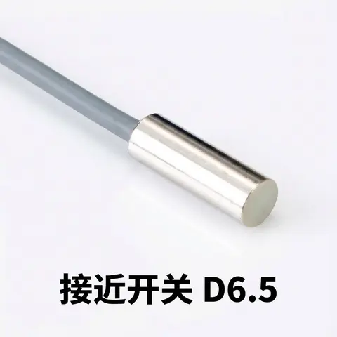
D6.5 Series Inductive Proximity Sensors (Ultra-Short 18mm / Y-Type / 35mm / 45mm)
6.5mm-diameter inductive proximity sensors for tight-clearance mounting where M8 sensors won't fit.
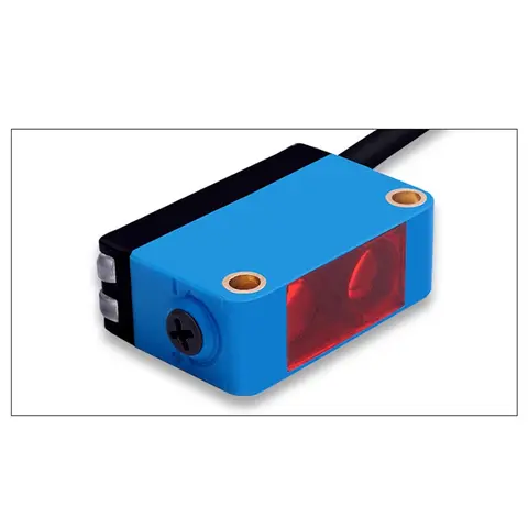
BGS-CX441 / BGS-CX442 Background Suppression Photoelectric Sensor
Wire-adjustable BGS sensor with 2 mm or 15 mm spot, 10-300 mm range, published black/white differential distance.
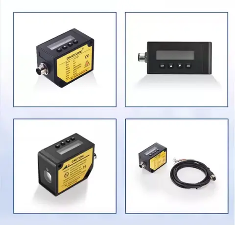
DDA-Y & DDB-Y Industrial Laser Distance Sensor (Phase-Shift)
Phase-shift laser distance sensors: 0.2-100 m range, millimeter accuracy, RS485 Modbus RTU, switching or analog output.
Related Products in Relay & Timer Modules
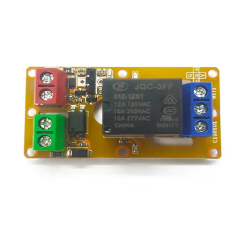
A1J0101 Economical Input Amplifier Module
Optocoupler-isolated input amplifier that turns a low-voltage signal into a 250V AC / 10A relay output.
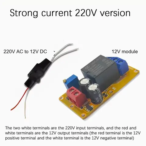
B2J0101 Economical Power-up Delay Module
Low-cost power-up delay relay module with a 2-30 second adjustable delay and no trigger input required.
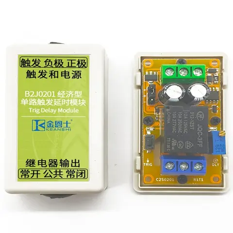
B2J0201 Economical Trigger Delay Module
Level-triggered delay relay module with jumper-selectable high/low trigger and a 2-30s adjustable delay.
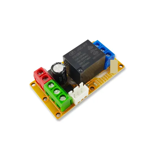
B2J0302 Enhanced Single MODBUS-485 I/O Module
Enhanced single-channel MODBUS-RTU/RS-485 I/O module: 1 digital input, 2 analog inputs, 1 relay or transistor output, AT command support and a 5V sensor supply — the successor to the discontinued B2J0301.