
D3J0214 Modbus
14-channel Modbus-RTU/RS-485 relay/transistor output module; optional PWM/PTO uses existing DO0/DO1 channels.
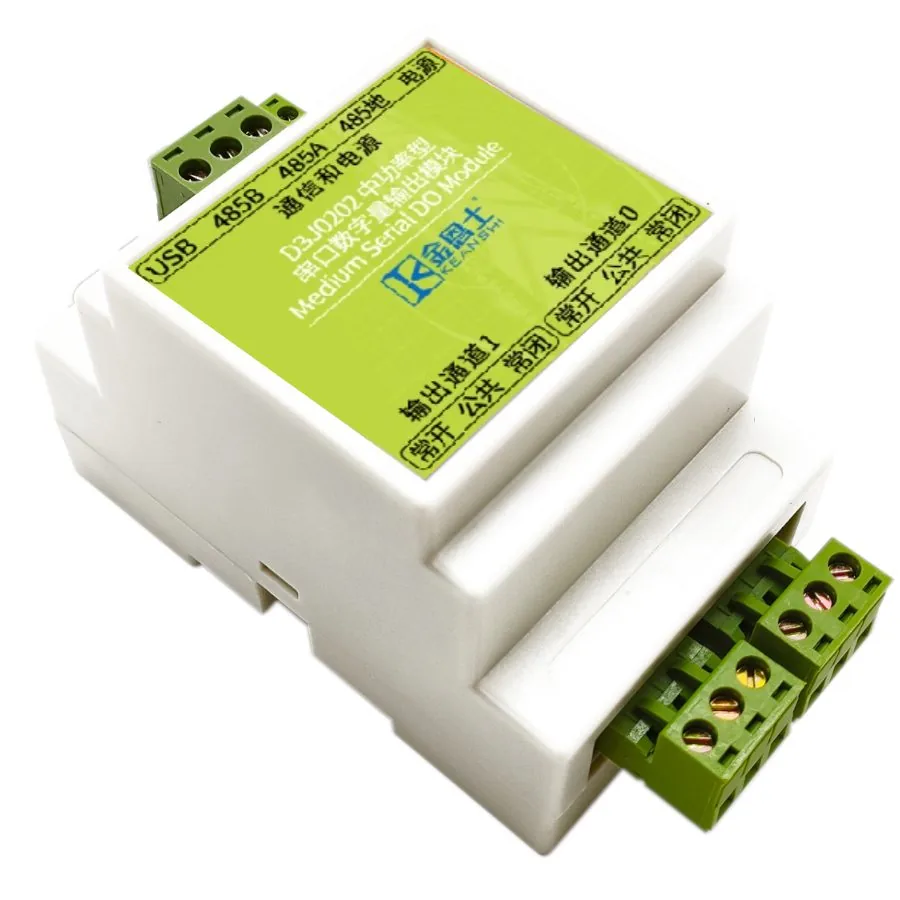 🔍 Click to enlarge · 1/4
ℹ Product photo shows KEANSHI (金恩士) housing markings — KEANSHI is a DAIDISIKE (戴迪斯科) group brand, and these D3-series serial I/O modules are supplied under it. The photo is a D3-series housing shot; the pictured unit carries D3J0202 markings — channel count and terminal layout follow the specification table above.
Technical Specifications
| Order Code | D3J0214M111 (default: all-relay output, pulse output not enabled, no wireless) |
|---|---|
| Product ID / Default Address Code | 0x3214 |
| Inputs | None (output-only) |
| Outputs | 14 fully isolated digital output channels (relay or transistor type, specified at order time); up to two of these channels (DO0/DO1) can be configured for PWM/PTO in the pulse-enabled version. Pulse mode does not add channels. |
| Communication Interface | RS-485 (Modbus-RTU, default 9600/8-E-1); optional 2.4GHz wireless |
| Supply Voltage | DC 11-28V |
| Default Baud Rate | 9600 bps |
| Default Data Format | 8 data bits, even parity, 1 stop bit |
| Default Slave Address | 0x02 |
| Selectable Baud Rates | 300 / 600 / 1200 / 1800 / 2400 / 4800 / 7200 / 9600 / 14400 / 19200 / 28800 / 38400 / 56000 / 57600 / 76800 / 115200 |
| Selectable Parity | None / Odd / Even (default Even) |
| Selectable Stop Bits | 1 (default) / 1.5 / 2 |
| Slave Address Range | 1-247 (0x01-0xF7) |
| USB Mode Address | Fixed at 0x01 when USB is connected; RS-485 then switches to master mode |
| Coil Mapping (14-Channel) | Uses all 56 coils (up to 0x0037); unimplemented coils read as 0 |
| Supported Function Codes | 0x01 Read Coils, 0x05 Write Single Coil, 0x0F Write Multiple Coils, 0x03 Read Holding Registers, 0x06 Write Single Holding Register, 0x10 Write Multiple Holding Registers, 0x16 Mask Write, 0x17 Read/Write Multiple Holding Registers, 0x04 Read Input Registers, 0x11 Report Device ID |
| Supply Ripple | < 1Vp-p |
| Supply Current | < 1500mA |
| Communication Terminal Stress | DC 0-5V |
| Relay Output Rating | DC 30V or AC 0-220V, 8A |
| Standard Transistor Output Rating | DC 12-48V, 8A |
| High-Speed Transistor Output Rating | DC 12-24V, 8A |
| Communication Isolation Voltage | < 250V |
| Relay Output Isolation Voltage | < 250V |
| Transistor Output Isolation Voltage | < 130V |
| Operating Temperature | -20 ~ 60C |
| Storage Temperature | -40 ~ 85C |
| Relay Mechanical Life | 100,000+ cycles (10,000+ under heavy load) |
| Dimensions (14-Channel) | 158 x 88 x 59 mm |
| Terminal Pitch | 5.08 mm |
| Absolute Max Supply Voltage | DC 28V |
| Fuse (One-Time) | DC 250V, 3000mA, slow-blow |
| Absolute Max Standard Transistor Output | DC 55V, 10A |
| Absolute Max High-Speed Transistor Output | DC 40V, 10A |
| ESD Immunity | 4kV to all terminals, IEC 61000-4-2, criterion A |
| EFT Immunity | 2kV/5kHz/2min criterion A; 4kV/5kHz/2min criterion C, IEC 61000-4-4 |
| Surge Immunity | 1kV all terminals to ground, criterion C, IEC 61000-4-5 |
Overview
The D3J0214 is a 14-channel Modbus-RTU/RS-485 digital output module built around a dedicated ASIC, designed for output-only control of relays, contactors, solenoid valves, and other loads from a host controller over a serial bus. It is the 14-channel member of the D3J02 series (2/4/8/14-channel siblings), with each channel individually available as relay or transistor output; the default order code is D3J0214M111 (all-relay output, pulse output not enabled, no wireless).
Communication defaults to 9600 bps, 8 data bits, even parity, 1 stop bit over RS-485, with slave addresses selectable from 1 to 247 and baud rate selectable across 16 steps from 300 to 115200 bps. A USB port is included for configuration and also works as USB-to-serial, and up to 2 of the 14 channels can be configured as high-speed transistor outputs for PWM speed control or PTO stepper/motor drive. Supply is DC 11-28V, and outputs are electrically isolated from the internal logic (relay isolation <250V, transistor isolation <130V).
Features & Benefits
14 Isolated Points From One Bus Address
Fourteen NC/COM/NO channels live in a single 158 x 88 x 59 mm node, so one slave address and one A/B drop replace up to seven 2-channel boards. That is one set of 56 coils (0x0000-0x0037) to poll instead of seven separate nodes to address, wire, terminate and troubleshoot - and one part number to stock.
Relay or Transistor Output, Same Board, Same Terminals
The M[ddd] order code's first digit picks the output stage: relay type switches DC 30V or AC 0-220V at 8A with 100,000+ mechanical cycles, transistor type is open-drain at DC 12-48V / 8A with a built-in 10A flyback diode that drives solenoids and motors directly - no external suppression diode to add. Same footprint, same wiring, so you can change the decision late without redrawing the panel.
Up to Two of Fourteen Outputs Configurable for PWM/PTO
With the two-channel pulse-enabled code selected, existing DO0/DO1 become high-speed FET outputs running standard PWM, fast PWM or PTO from the on-board PGM memory at 0x0100, while DO2-DO13 stay ordinary switches. The total remains 14 outputs; a DO0-only pulse configuration allocates only one existing channel. Confirm the receiving drive or load interface separately.
Each Channel Is Its Own Little Controller
Every output carries four coils - DOUTnDV value, DOUTnRST reset, DOUTnFV force value, DOUTnFEN force enable - plus a DOUTnCFG register from 0x0080 with a momentary/delay timer. Rotational irrigation, staged starts and timed dosing keep running inside the module, so they do not depend on master ladder logic or on bus poll latency.
Force Bits for Commissioning Without Touching Host Code
DOUTnFV and DOUTnFEN let a technician override any single channel to a known state from a laptop while the host keeps writing normally. You can ring out 14 valves during startup, or bench-test a load, without editing and re-downloading PLC logic.
SAFELCK Stops a Noisy Bus From Rewriting Your Settings
Sensitive registers (NAME, SRLCFG serial config, wireless keys) refuse writes until ASCII "UL" (0x554C) is written to SAFELCK at 0x000E - and the lock re-arms after every single write, and again on any CRC error or on any command addressed to another module. A corrupted frame on a long RS-485 run cannot silently change your baud rate or slave address.
Protection Designed In, With Measured Margin
The supply survives reverse connection, overcurrent, surge and automotive load dump behind a DC 250V / 3000mA slow-blow fuse; comms and outputs are galvanically isolated from the logic (relay < 250V, transistor < 130V). PCB creepage measures > 6.5 mm against the > 6 mm required and clearance > 2.2 mm against > 2 mm (IEC 60950, pollution degree 3), and ESD 4kV to all terminals gives criterion A per IEC 61000-6-2.
USB Port Included - Commission It With No Converter
The on-board USB works as configuration port, firmware channel and USB-to-serial adapter; plug it in and the module fixes itself at address 0x01 while RS-485 flips to master, so one D3J0214 can drive and test the rest of the bus. MODBUS-ASCII eases touch-panel and PLC integration, AT commands cover quick jobs, and 2.4GHz wireless MODBUS-OTA is an order option. Supply is DC 11-28V, so 12V and 24V panels both work off one part number.
Applications
Models & Ordering Information
D3J0214 (14-Channel)
How to Select
- Choose the 14-channel D3J0214 when 9-14 output points need single-board density and minimal wiring; step down to the 8-channel D3J0208, 4-channel D3J0204, or 2-channel D3J0202 for fewer points.
- Choose relay-type output for switching AC 220V, driving contactors, AC valves, or indicator lamps, or when the load is sensitive to the ~50ms transient pulse that can occur at power-up/power-down.
- Choose transistor-type output for inductive DC loads, high-frequency frequent switching, long service life, or when PWM/PTO pulse output is required, since the pulse function is transistor-type only.
- For PWM/PTO, specify the DO0-only or DO0/DO1 pulse-enabled configuration. One or two existing outputs are allocated to high-speed pulse operation; any remaining channels stay as ordinary switching outputs. Pulse mode does not increase the 14-channel total.
- The listed <1500mA is the module's own supply-current figure, not an established shared budget for switched loads. Check individual output/contact ratings, the external load supply, terminal/wiring limits and permitted simultaneous loading separately using the current instructions.
📘 Need the full method? NPN vs PNP Sensor Outputs Explained
When NOT to specify the D3J0214 — and what to use instead
The same panel needs to read a dozen or more digital inputs (position switches, level switches) as well as switch a dozen outputs
Why not: The D3J0214's own spec states Inputs: "None (output-only)" - it has zero acquisition channels no matter how many of its 14 outputs are used
Use instead: D3J0312 (combined input/output module) or a D3J0128 input module run alongside it on the same bus
The application only has 4-6 output points, inside a compact enclosure
Why not: The D3J0214 is 158mm long to carry 14 channels - excess board length, terminal count and per-point cost for a handful of switching points
Use instead: step down to D3J0208, D3J0204 or D3J0202
More than 14 independent outputs are needed from a single node, such as a very large valve farm
Why not: The D3J0214's 14-channel coil map already uses all 56 available coils (0x0000-0x0037); there is no larger channel-count member in the D3J02 series
Use instead: add a second D3J0214 (or another D3J02 member) at a different slave address on the same RS-485 bus - up to 247 addresses are supported
Many output channels are used simultaneously, especially with inductive loads
Why not: The module's listed <1500mA supply current and the load-side output ratings are different quantities. This page does not establish aggregate switched-load capacity or a permitted simultaneous-load limit.
Use instead: Obtain the current model-specific wiring and simultaneous-load limits; size the module supply and external load supply separately and confirm any protection required by the loads.
One or more of the 14 channels forms part of an emergency-stop or safety-interlock circuit
Why not: No Type/SIL/PL safety rating applies to the D3J0214; its relay and transistor outputs are ordinary industrial contacts, not OSSDs
Use instead: DA31 Emergency-Stop Safety Relay Module or DQSRN Safety Relay Module
Specifications we do not publish yet
We only publish a figure once we are confident it is true. The items below are still being validated through further testing and real-world customer feedback, so for now we would rather leave them open than guess. If one of them matters to your design, ask us for the latest validated status.
- Relay contact (electrical) life at rated 8A load, separate from the published mechanical-cycle figures
- MTBF for the D3J0214 module
- Relay manufacturer and part number fitted to the D3J0214
- Recommended wire gauge and torque for the 14 sets of NC/COM/NO screw terminals
- Ingress protection (IP) rating of the housing
- Maximum validated RS-485 node count and cable length on one trunk carrying multiple D3J0214-class modules
- Module net weight
- Specific certification marks obtained (CE/UL/RoHS etc.)
Frequently Asked Questions
What is the difference between relay-type and transistor-type outputs on the D3J0214?
Can the D3J0214 read digital inputs?
How many of the 14 channels can output PWM or PTO pulses?
What communication settings does the D3J0214 use by default?
Does the D3J0214 come with certification documents?
Is there a risk of the outputs switching on briefly during power-up or power-down?
Can the D3J0214 be configured over USB instead of RS-485?
Related Categories and Example Products
Explore other functions that may be needed in a machine or line. The products below are category examples, not pre-validated electrical or safety combinations. Confirm each interface and application separately: Proximity Sensors · Photoelectric Sensors · Laser Distance Sensors
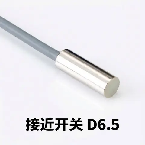
D6.5 Series Inductive Proximity Sensors (Ultra-Short 18mm / Y-Type / 35mm / 45mm)
6.5mm-diameter inductive proximity sensors for tight-clearance mounting where M8 sensors won't fit.
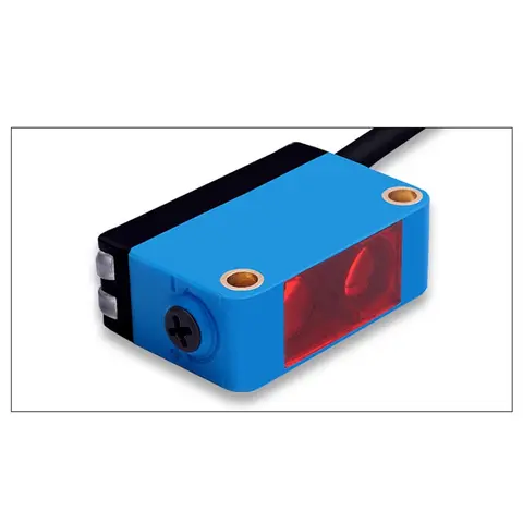
BGS-CX441 / BGS-CX442 Background Suppression Photoelectric Sensor
Wire-adjustable BGS sensor with 2 mm or 15 mm spot, 10-300 mm range, published black/white differential distance.
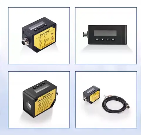
DDA-Y & DDB-Y Industrial Laser Distance Sensor (Phase-Shift)
Phase-shift laser distance sensors: 0.2-100 m range, millimeter accuracy, RS485 Modbus RTU, switching or analog output.
Related Products in Relay & Timer Modules
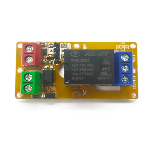
A1J0101 Economical Input Amplifier Module
Optocoupler-isolated input amplifier that turns a low-voltage signal into a 250V AC / 10A relay output.
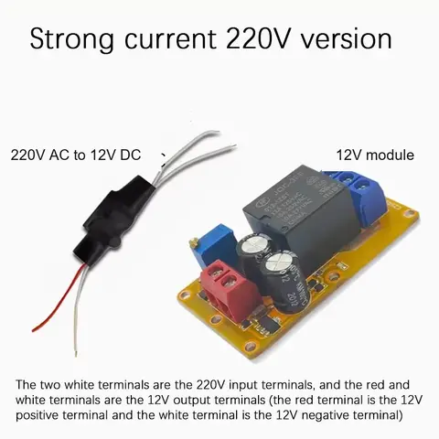
B2J0101 Economical Power-up Delay Module
Low-cost power-up delay relay module with a 2-30 second adjustable delay and no trigger input required.
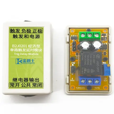
B2J0201 Economical Trigger Delay Module
Level-triggered delay relay module with jumper-selectable high/low trigger and a 2-30s adjustable delay.
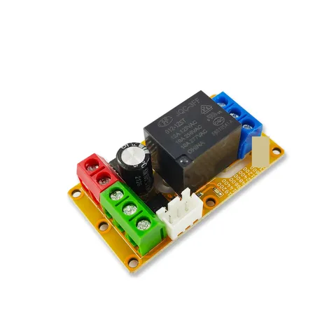
B2J0302 Enhanced Single MODBUS-485 I/O Module
Enhanced single-channel MODBUS-RTU/RS-485 I/O module: 1 digital input, 2 analog inputs, 1 relay or transistor output, AT command support and a 5V sensor supply — the successor to the discontinued B2J0301.