
D3J0208 Modbus
8-channel Modbus-RTU/RS-485 relay/transistor output module; optional PWM/PTO uses existing DO0/DO1 channels.
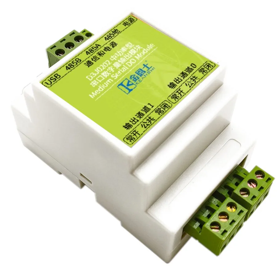 🔍 Click to enlarge · 1/4
ℹ Product photo shows KEANSHI (金恩士) housing markings — KEANSHI is a DAIDISIKE (戴迪斯科) group brand, and these D3-series serial I/O modules are supplied under it. The photo is a D3-series housing shot; the pictured unit carries D3J0202 markings — channel count and terminal layout follow the specification table above.
Technical Specifications
| Order Code (default) | D3J0208M111 (relay output, pulse not available, no wireless) |
|---|---|
| Product ID / Default Slave Address | 0x3208 |
| Input | None (pure output type) |
| Output | 8 fully isolated digital output channels (relay or transistor type, specified at order time); up to two of these channels (DO0/DO1) can be configured for PWM/PTO in the pulse-enabled version. Pulse mode does not add channels. |
| Communication Interface | RS-485 (Modbus-RTU, default 9600/8-Even-1); optional 2.4GHz wireless |
| Physical Interface | RS-485 half-duplex, differential twisted pair A/B; plus USB port; optional 2.4GHz wireless Modbus-OTA |
| Communication Protocol | Modbus-RTU (primary); plus Modbus-ASCII, AT commands; wireless Modbus-OTA |
| Default Baud Rate | 9600 bps |
| Default Data Format | 8 data bits, even parity, 1 stop bit |
| Default Slave Address | 0x02 |
| Optional Baud Rates | 300 / 600 / 1200 / 1800 / 2400 / 4800 / 7200 / 9600 / 14400 / 19200 / 28800 / 38400 / 56000 / 57600 / 76800 / 115200 bps |
| Optional Parity | None / Odd / Even (default Even) |
| Optional Stop Bits | 1 (default) / 1.5 / 2 |
| Slave Address Range | 1-247 (0x01-0xF7) |
| USB Mode Address | Fixed at 0x01 when USB is connected; RS-485 then switches to master mode |
| Output Coil Mapping | Each output channel occupies one coil; 8-channel type uses coils up to 0x001F (full 32); unimplemented coils read as 0 |
| Auto-Reporting | Supports active reporting at intervals (AT format, selectable USB or RS-485 port); default off |
| Supply Voltage | DC 11-28V |
| Supply Ripple | < 1Vp-p |
| Supply Current | < 1500mA |
| Communication Port Stress | DC 0-5V |
| Output Stress (Relay Type) | DC 30V or AC 0-220V, 8A |
| Output Stress (Standard Transistor Type) | DC 12-48V, 8A |
| Output Stress (High-Speed Transistor Type) | DC 12-24V, 8A |
| Communication Isolation Voltage | < 250V |
| Output Isolation Voltage (Relay Type) | < 250V |
| Output Isolation Voltage (Transistor Type) | < 130V |
| Operating Temperature | -20 to 60C |
| Max Supply Voltage (absolute) | DC 28V |
| One-Time Fuse | DC 250V, 3000mA, slow-blow |
| Max Communication Port Stress (absolute) | DC 50V |
| Max Output Stress (Relay Type, absolute) | DC 30V or AC 0-220V, 8A |
| Max Output Stress (Standard Transistor Type, absolute) | DC 55V, 10A |
| Max Output Stress (High-Speed Transistor Type, absolute) | DC 40V, 10A |
| Max Communication Isolation Voltage (absolute) | DC 1000V, 60 seconds (type test only) |
| Max Output Isolation Voltage (Relay Type, absolute) | DC 1000V, 60 seconds (type test only) |
| Max Output Isolation Voltage (Transistor Type, absolute) | DC 250V, 60 seconds (type test only) |
| Relay Mechanical Life | Over 100,000 operations (over 10,000 under heavy load) |
| Storage Temperature | -40 to 85C |
| ESD Immunity | 4kV to all terminals -> normal operation (Criterion A) |
| EFT Immunity | 2kV/5kHz/2min -> normal (A); 4kV/5kHz/2min -> no permanent damage (C) |
| Surge Immunity | 1kV, all terminals to ground -> no permanent damage (C) |
| Creepage Distance | > 6.5mm measured (requirement > 6mm, pollution degree 3) |
| Clearance | > 2.2mm measured (requirement > 2mm, pollution degree 3) |
| Module Dimensions (L x W x H) | 107 x 88 x 59mm (tolerance +/-5%) |
| Terminal Pitch | 5.08mm |
Overview
The D3J0208 is an 8-channel fully isolated digital output module built around a dedicated ASIC and communicating over RS-485 using the Modbus-RTU protocol. It is a pure output device with no input acquisition, designed for machine builders, panel integrators, and building automation engineers who need to centrally switch 5-8 relays, solenoid valves, contactors, or indicator lights from a single machine or a small-to-medium control cabinet onto one board.
Each of the 8 channels is independently configurable as a relay output (DC 30V or AC 0-220V, 8A, mechanical life over 100,000 operations) or a transistor output (open-drain, DC 12-48V, 8A, with a built-in flyback diode for direct driving of inductive loads), and up to two existing channels (DO0/DO1) can be ordered as high-speed PWM/PTO pulse outputs for motor speed control or stepper driving. The module communicates over RS-485 at a default of 9600 bps, 8 data bits, even parity, 1 stop bit, and slave address 0x02, with a supported address range of 1-247, and also includes a USB port, Modbus-ASCII, AT commands, and an optional 2.4GHz wireless link.
Features & Benefits
One Board Replaces a Row of Interposing Relays
Eight channels each bring out NC/COM/NO screw terminals - 24 output terminals on a 5.08mm pitch inside a 107 x 88 x 59mm housing. Relay contacts switch AC 0-220V or DC 30V at 8A directly, so eight valves, contactors or pumps run from one module and one twisted pair instead of eight home-run cables, a DIN rail of interposing relays and a spare PLC output card.
Relay or Transistor Output - Ordered to Match the Load
The order code selects the output stage: digit 1 of D3J0208M[ddd] is 1 for relay or 2 for FET. Relay type gives under-250V isolation, switches AC mains and lasts over 100,000 mechanical operations. Transistor type is open-drain, rated DC 12-48V at 8A with a built-in 10A flyback diode, so it drives large solenoids and DC motors directly - no external suppression diode, no contact wear from high-frequency switching.
Up to Two of Eight Outputs Configurable for PWM/PTO
Depending on the pulse-enabled order code (digit 2 = 3 or 4), DO0 only or DO0/DO1 are configured as high-speed transistors for standard PWM, fast PWM and standard PTO pulse-train output from the PGM memory at 0x0100, rated DC 12-24V at 8A. With both pulse channels selected, the six remaining channels provide ordinary switching. All of these functions use the existing eight outputs; confirm the receiving drive or load interface separately.
Local Delay Timer Keeps Sequences Running Without the Master
Every channel has four coils (DOUTnDV value, DOUTnRST reset, DOUTnFV forced value, DOUTnFEN force enable) and a DOUTnCFG register from 0x0080 that can turn it into a simple jog/delay timer with its own power-on default state. Timed dosing, purge cycles or rotational irrigation run locally, so the bus is not tied up polling and the sequence survives a busy or briefly offline master. DOUTnFV/DOUTnFEN also give maintenance staff a forced override per channel.
A Config Lock That Survives a Noisy Bus
Sensitive registers (device name, serial config, wireless keys) cannot be written until ASCII 'UL' (0x554C) is written to SAFELCK at 0x000E, and the lock re-arms after every single write. A CRC error on the bus, or any frame addressed to another module, re-locks it too. On a shared RS-485 trunk in a noisy plant, that is what stops a garbled frame from silently changing this module's baud rate and dropping it off the network.
Isolation and Clearance You Can Audit, Not Just Claim
The RS-485 port and all outputs are galvanically isolated from the internal logic - under 250V for relay outputs, type tested at DC 1000V for 60 seconds. On the PCB, the high-voltage side is slotted for creepage: measured over 6.5mm against the 6mm requirement, and clearance over 2.2mm against 2mm, at pollution degree 3 with material group IIIa/IIIb per IEC60950. The numbers are measured margins over the standard, not the bare minimum.
Built for Plant Electrical Noise and Vehicle Power
Tested to IEC61000-6-2 industrial immunity: ESD 4kV to all terminals with normal operation (criterion A), EFT 2kV/5kHz for 2 minutes at criterion A and 4kV without permanent damage, and 1kV surge to ground without permanent damage. The DC 11-28V input is protected against reverse polarity, overcurrent, surge and automotive load dump and is backed by a DC 250V/3000mA slow-blow fuse, so the same module suits a 24V panel or a vehicle supply from -20 to 60C.
Commission With a Laptop; Retrofit Without Rewiring
Besides RS-485 the module carries a USB port that doubles as a USB-to-serial adapter: plug in and the module answers at address 0x01 while its RS-485 port turns master, so you can bench-test the whole bus from a PC with no PLC present. Modbus-ASCII and character-mode AT commands ease integration with touch screens, and interval auto-reporting is available on either port. For retrofits where new conduit is impractical, order the 2.4GHz self-organising Modbus-OTA option instead.
Applications
Models & Ordering Information
D3J0208
How to Select
- Choose the 8-channel D3J0208 when a single machine or panel has 5-8 output points; for fewer points use the 4-channel D3J0204 or 2-channel D3J0202, and for more than 8 points on one board use the 14-channel D3J0214.
- Choose the relay type to switch AC 220V, drive contactors, AC valves, or indicator lights, or when the controlled load is sensitive to the brief ~50ms pulse during power-on/power-off.
- Choose the transistor type for DC inductive loads, high-frequency frequent switching, longer service life, or when PWM/PTO pulse output is needed (pulse output is available on the transistor type only).
- For PWM/PTO, specify the DO0-only or DO0/DO1 pulse-enabled configuration. One or two existing outputs are allocated to high-speed pulse operation; any remaining channels stay as ordinary switching outputs. Pulse mode does not increase the 8-channel total.
📘 Need the full method? NPN vs PNP Sensor Outputs Explained
When NOT to specify the D3J0208 — and what to use instead
The panel also needs to read 4-8 field digital inputs (limit switches, flow switches, float switches) on the same board that does the switching
Why not: The D3J0208's own spec lists Input as "None (pure output type)" - it has zero input acquisition circuitry regardless of its 8 output channels
Use instead: D3J0308 (combined input/output module) or pair it with a D3J0108 input module on the same RS-485 bus
Only 2-4 output points are actually needed for a small skid or a single machine
Why not: The D3J0208 ships in a 107 x 88 x 59mm housing with 24 output terminals sized for 8 channels - unnecessary DIN-rail space and per-point cost for a handful of switching points
Use instead: D3J0204 (4-channel) or D3J0202 (2-channel)
More than 8 independent output points must live on a single node, such as a 10+ zone valve manifold
Why not: The D3J0208's coil map is fixed at 0x0000-0x001F (32 coils covering 8 channels); there are only 8 physical output channels on this model
Use instead: D3J0214 (14-channel)
Several of the 8 channels will drive AC-mains contactors or heater banks that cycle rapidly and continuously
Why not: The D3J0208's relay mechanical life is rated over 100,000 operations in general use, dropping to over 10,000 operations under heavy load - rapid-cycle switching consumes that life quickly
Use instead: order the transistor/MOSFET-type variant for the DC portion of the load, or route high-cycle AC loads through an externally rated contactor driven by the module
Any of the 8 outputs is wired into a machine guard-door lock, E-stop chain or other safety function
Why not: The D3J0208 carries no safety rating in its spec; it is a standard industrial output module, not a safety relay, and its outputs are not OSSDs
Use instead: DA31 Emergency-Stop Safety Relay Module or DQSRN Safety Relay Module
The host backbone runs a fieldbus other than Modbus-RTU, such as an existing EtherCAT or Profinet network
Why not: The only network interfaces documented for the D3J0208 are RS-485 Modbus-RTU, USB, and the optional 2.4GHz Modbus-OTA wireless link
Use instead: add a protocol gateway ahead of the module
Specifications we do not publish yet
We only publish a figure once we are confident it is true. The items below are still being validated through further testing and real-world customer feedback, so for now we would rather leave them open than guess. If one of them matters to your design, ask us for the latest validated status.
- Relay contact (electrical) life at rated 8A load, as distinct from the published mechanical-cycle count
- MTBF for the D3J0208 module
- Relay manufacturer and part number used in the D3J0208
- Recommended wire gauge and torque for the 8 sets of NC/COM/NO screw terminals
- Ingress protection (IP) rating of the housing
- Maximum validated number of RS-485 nodes and cable length on one bus
- Module net weight
- Specific certification marks obtained (CE/UL/RoHS etc.)
Frequently Asked Questions
What is the D3J0208 used for?
What is the difference between the relay and transistor output versions?
Can the D3J0208 output PWM or PTO pulses?
What happens to the outputs at power-on and power-off?
Can the D3J0208 be configured or operated over USB instead of RS-485?
Does the D3J0208 have any certifications?
Related Categories and Example Products
Explore other functions that may be needed in a machine or line. The products below are category examples, not pre-validated electrical or safety combinations. Confirm each interface and application separately: Proximity Sensors · Photoelectric Sensors · Laser Distance Sensors
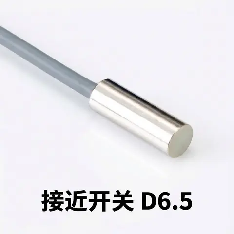
D6.5 Series Inductive Proximity Sensors (Ultra-Short 18mm / Y-Type / 35mm / 45mm)
6.5mm-diameter inductive proximity sensors for tight-clearance mounting where M8 sensors won't fit.
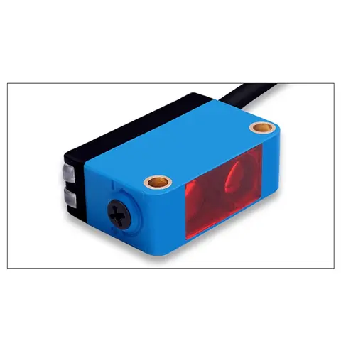
BGS-CX441 / BGS-CX442 Background Suppression Photoelectric Sensor
Wire-adjustable BGS sensor with 2 mm or 15 mm spot, 10-300 mm range, published black/white differential distance.
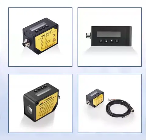
DDA-Y & DDB-Y Industrial Laser Distance Sensor (Phase-Shift)
Phase-shift laser distance sensors: 0.2-100 m range, millimeter accuracy, RS485 Modbus RTU, switching or analog output.
Related Products in Relay & Timer Modules
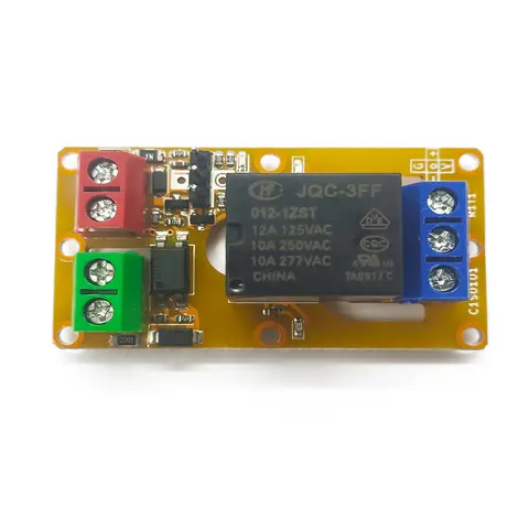
A1J0101 Economical Input Amplifier Module
Optocoupler-isolated input amplifier that turns a low-voltage signal into a 250V AC / 10A relay output.
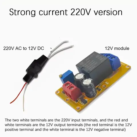
B2J0101 Economical Power-up Delay Module
Low-cost power-up delay relay module with a 2-30 second adjustable delay and no trigger input required.
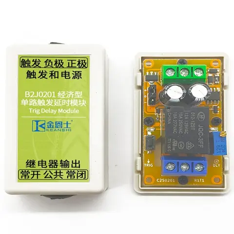
B2J0201 Economical Trigger Delay Module
Level-triggered delay relay module with jumper-selectable high/low trigger and a 2-30s adjustable delay.
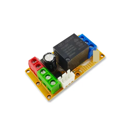
B2J0302 Enhanced Single MODBUS-485 I/O Module
Enhanced single-channel MODBUS-RTU/RS-485 I/O module: 1 digital input, 2 analog inputs, 1 relay or transistor output, AT command support and a 5V sensor supply — the successor to the discontinued B2J0301.