
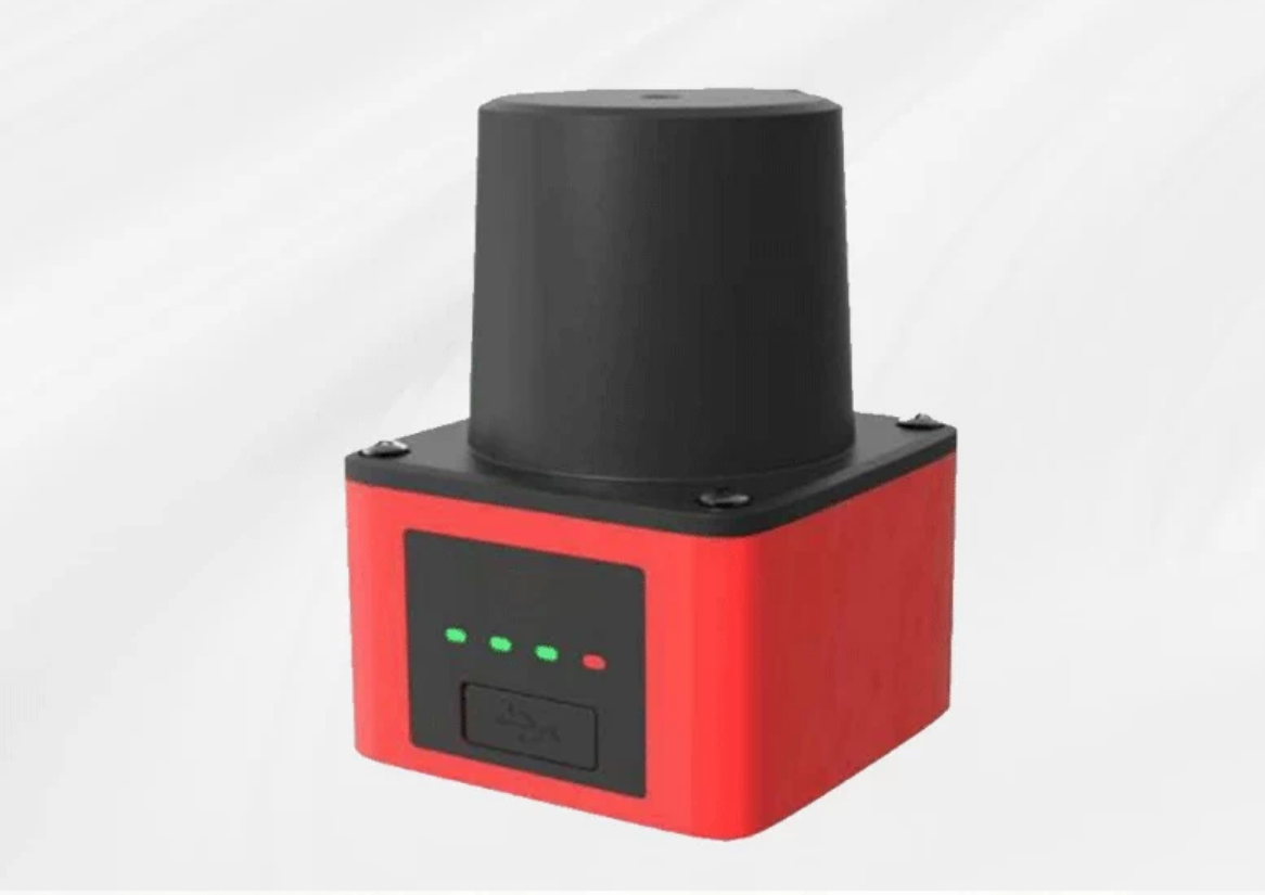
SDLD-05A TOF Laser Radar (Obstacle-Avoidance Type)
A 270° TOF laser radar with 0.1-14m range and 16 switchable zones for AGV/RGV obstacle avoidance.
 🔍 Click to enlarge · 1/3
Technical Specifications
| Model | SDLD-05A |
|---|---|
| Detection Range | 0.1-14m at 90% target reflectivity; 0.1-8m at 10% target reflectivity |
| Scanning Angle | 270° |
| Detection Accuracy | ±30mm |
| Repeatability | ≤20mm |
| Angular Resolution | 0.5° |
| Scanning Frequency | 20Hz |
| Response Time (manual specification) | 50ms; configured response and hold filters also affect output behavior |
| Configurable Hold/Response Time (software) | Adjustable; factory defaults are not established by the supplied manual |
| Detection Zones | 16 switchable zone groups, each with 3 independently editable sub-zones |
| Zone Shapes | Polygon (up to 15 vertices), fan, rectangle |
| Zone Group Selection | IN1-IN4 select 16 groups. In IN4-IN3-IN2-IN1 order: 1111 selects group 0; 0000 selects group 15. |
| Communication Interface | Ethernet (RJ45); UDP connection for configuration software |
| Digital I/O | 4 NPN inputs; 3 zone outputs (OUT1-OUT3) plus reserved OUT4; output load capacity <10mA. Zone outputs go low when their corresponding obstacle indicators are on. |
| Local Configuration Port | USB Type-C |
| Laser | 905nm (TOF) |
| Housing Material | Aluminum-alloy body with plastic cover (standard color red) |
| Dimensions | 61×61×82mm |
| Weight | 374g including cable |
| Power Supply | DC 9-36V (typical 12V) |
| Power Consumption | ≤2.5W |
| Operating Temperature | -10°C to 50°C |
| Storage Temperature | -20°C to 55°C |
| Humidity | <85%RH, no condensation or frost |
| Ingress Protection | IP54 |
| Shock Resistance | 196m/s² (20G), 10 times per axis |
| EMC Standards Referenced | EN 61000-6-2:2005, EN 61000-6-4:2007+A1 (listed in the manual; not a stated laser class or functional-safety rating) |
Overview
The SDLD-05A is a Time-of-Flight (TOF) 2D laser radar designed for obstacle-avoidance and area detection on indoor/outdoor mobile equipment. Per the manufacturer's own documentation, its typical application cases are Automated Guided Vehicles (AGV) and Rail Guided Vehicles (RGV). It is built for AGV/AMR integrators, machine builders, and industrial automation OEMs who need a single sensor to detect obstacles across a 270° field of view and switch between multiple pre-configured detection zones as the vehicle changes direction or speed.
The sensor delivers a 270° scan at 20Hz with a 0.1-14m detection range (at 90% target reflectivity; 0.1-8m at 10% reflectivity), ±30mm measurement accuracy, and ≤20mm repeatability at 0.5° angular resolution. Detection is organized into 16 switchable zone groups, each with 3 independently editable sub-zones, selected through inputs IN1-IN4 and configured visually over Ethernet (RJ45, UDP). NPN zone outputs provide obstacle-status signals to a compatible vehicle or machine controller; OUT1-OUT3 serve the three zones and OUT4 is reserved.
SDLD-05A Installation and Zone-Selection Checks
Start with the scan plane and the actual target. The manual recommends mounting at least 200mm above the floor; below 200mm, its installation text specifies an upward tilt of 1-3°. For units whose scan planes cross, it recommends a tilt of at least 3° or a vertical offset of at least 40mm to reduce mutual interference. Check the resulting coverage in the installed position, including the 270° scan boundary and objects that may be hidden by the vehicle body.
The manual's zone-selection table uses the column order IN4, IN3, IN2, IN1. Follow the states below when checking each configured group: 1111 selects group 0, while 0000 selects group 15. The 0 and 1 entries are reproduced as table states; the manual does not give input voltage thresholds here. Match the supplied unit's wiring instructions before connecting the controller.
| Zone group | IN4 | IN3 | IN2 | IN1 |
|---|---|---|---|---|
| 0 | 1 | 1 | 1 | 1 |
| 1 | 1 | 1 | 1 | 0 |
| 2 | 1 | 1 | 0 | 1 |
| 3 | 1 | 1 | 0 | 0 |
| 4 | 1 | 0 | 1 | 1 |
| 5 | 1 | 0 | 1 | 0 |
| 6 | 1 | 0 | 0 | 1 |
| 7 | 1 | 0 | 0 | 0 |
| 8 | 0 | 1 | 1 | 1 |
| 9 | 0 | 1 | 1 | 0 |
| 10 | 0 | 1 | 0 | 1 |
| 11 | 0 | 1 | 0 | 0 |
| 12 | 0 | 0 | 1 | 1 |
| 13 | 0 | 0 | 1 | 0 |
| 14 | 0 | 0 | 0 | 1 |
| 15 | 0 | 0 | 0 | 0 |
- Draw the three zones for each required group as polygons, sectors or rectangles, save the configuration as an .ini file, and download it to the sensor. Use Monitor mode to check that the displayed group follows the controller's selected input state.
- Check OUT1, OUT2 and OUT3 separately with a representative obstacle. The manual maps them to the blue, yellow and red obstacle indicators respectively and states that the corresponding output is low when its indicator is on. OUT4 is reserved; the specified output load is below 10mA.
- Record the actual response-time, hold-time and object-size settings before checking detection. The manual lists 50ms response time and separately describes adjustable filters, but does not establish factory defaults or a complete-system stopping time.
- Verify the required range with the darkest and smallest expected targets. The 14m figure is specified at 90% reflectivity; at 10% reflectivity the listed maximum is 8m. A successful obstacle-detection check does not establish a personnel-safety rating.
These checks follow the supplied SDLD-05A manual's parameter table, input-state table, installation guidance and software instructions (PDF pages 2, 4, 6 and 11-18). Before a sample evaluation, use the 2D LiDAR selection guide to define target and controller requirements, and compare the documented configuration paths in the LiDAR product range.
Features & Benefits
270° single-sensor coverage with 0.1-14m TOF ranging
A 270° scan can support forward and lateral obstacle detection when positioned for the required vehicle coverage. The manual specifies 0.1-14m range at 90% target reflectivity and 0.1-8m at 10% target reflectivity, with ±30mm measurement accuracy, ≤20mm repeatability, 20Hz scanning frequency and 0.5° angular resolution.
16 switchable zone groups, each with 3 independently editable sub-zones
Zone shapes can be drawn as polygon (up to 15 vertices), fan, or rectangle, and combined freely. Inputs IN1-IN4 select 16 saved configurations without re-programming the sensor. In the manual's IN4-IN3-IN2-IN1 order, 1111 selects group 0 and 0000 selects group 15.
Ethernet configuration and NPN obstacle-status outputs
The manual documents an Ethernet (RJ45, UDP) connection for the configuration software and NPN outputs for obstacle-status signals. OUT1-OUT3 correspond to the three zones; OUT4 is reserved. Outputs go low when the respective obstacle indicators are on, and the specified output load is <10mA. Confirm electrical compatibility with the receiving controller. A USB Type-C configuration port is also provided.
PC configuration software with visual zone editing and live point-cloud display
Zones are drawn/edited on screen with the configuration software, saved and re-opened as .ini configuration files, downloaded to the sensor, and verified live via point-cloud display in either Edit mode or Monitor mode, which auto-switches to the active zone as the vehicle moves through different zone groups.
Configurable response filtering to suppress nuisance triggers
The manual lists a 50ms response time. The configuration software separately allows response-time filtering before an obstacle signal is asserted and hold-time filtering after the obstacle disappears, plus an object-size filter for small point clusters. Verify the selected values and resulting output timing during commissioning; the manual does not establish factory defaults.
Compact, wide-temperature-range metal housing rated IP54
Aluminum-alloy body with a plastic cover (standard color red), 61×61×82mm, 374g including cable, powered by DC 9-36V (typical 12V) at ≤2.5W, operating from -10°C to 50°C (storage -20°C to 55°C), humidity <85%RH without condensation or frost. The manual also lists shock conditions of 196m/s² (20G), 10 times per axis, and separate packaged and operating vibration conditions.
Applications
Models & Ordering Information
SDLD-05A Series
How to Select
- The 14m maximum range is rated at 90% target reflectivity; the manual lists 8m at 10% reflectivity. Verify the required detection distance using actual targets, including low-reflectivity surfaces, rather than treating the headline range as guaranteed for every object.
- Use Ethernet (UDP) with the configuration software for visual setup and diagnostics. The NPN zone outputs OUT1-OUT3 provide low-level obstacle signals when their corresponding indicators are on, with output load capacity <10mA. Confirm receiving-input compatibility; the manual does not establish a direct actuator or relay-coil drive capability.
- For a fixed detection area, use a rectangle or fan zone; for irregular outlines, edit a polygon point by point (up to 15 vertices). Where zones change with vehicle state, select among 16 preset groups using IN1-IN4 and check the complete input-state table in the installation section above.
- The manual recommends mounting at least 200mm above the floor. If mounted lower than 200mm, its installation text specifies an upward tilt of 1-3°; where multiple units cross-scan, it recommends a tilt of at least 3° or a vertical offset of at least 40mm to reduce mutual interference. Verify coverage after adjusting the mounting angle.
- Match the supply to DC 9-36V (typical 12V) and the listed ≤2.5W consumption. Confirm the supplied unit's cable identification, wiring instructions and controller interface before connection; wire color alone is not sufficient to resolve the manual's power-lead descriptions.
📘 Need the full method? How to Choose a 2D LiDAR Scanner
When NOT to specify the SDLD-05A — and what to use instead
Using the SDLD-05A as a safety-rated protective device because of its 'S' prefix or its AGV framing
Why not: The supplied manual does not establish an IEC 61496 Type, IEC 61508 SIL or ISO 13849 category/performance level. It documents NPN zone outputs with a load capacity below 10mA and does not specify OSSD safety outputs. Its model prefix and AGV examples do not establish a certified protective function.
Use instead: Select a protective device with model-specific evidence for the required safety function, and validate its integration into the complete machine or vehicle.
Exposure to washdown, water jets or conditions beyond the documented IP54 and operating-environment limits
Why not: The manual names indoor/outdoor equipment as applications but specifies IP54, -10°C to 50°C operation and <85%RH without condensation or frost. An outdoor application example does not establish suitability for every weather or cleaning condition.
Use instead: Select equipment whose documented enclosure and environmental limits meet the actual exposure. If an enclosure is proposed, verify both environmental protection and the scanner's optical coverage in the final installation.
Sizing the maximum detection distance off the headline 14 m figure for dark or matte targets
Why not: Range is explicitly tied to target reflectivity: 0.1-14m at 90% reflectivity and 0.1-8m at 10% reflectivity. The manual does not assign a reflectivity or guaranteed range to every material, color or surface finish.
Use instead: Use the 8m at 10% reflectivity specification when comparing low-reflectivity performance, then verify the required zone boundaries with representative targets under the intended conditions.
A control panel that needs PNP (sourcing) digital outputs
Why not: The supplied SDLD-05A manual documents NPN inputs and outputs. It does not establish a PNP option for this model.
Use instead: Confirm the receiving panel's electrical requirements and request a documented compatible output option before ordering.
Treating the listed 50ms response time as a guaranteed complete-system reaction time
Why not: The manual also documents adjustable response-time and hold-time filters. Its settings screenshot does not establish factory defaults or a formula for complete-system latency. Controller processing and actuator behavior must be assessed in the application.
Use instead: Record the actual filter settings, configure them for the required obstacle-detection behavior and measure the complete application response during commissioning.
Relying on it to flag very small or thin objects at its standard 0.5 degree angular resolution
Why not: The manual lists 0.5° angular resolution and an adjustable object-size filter, but does not give a guaranteed minimum detectable object size at each distance.
Use instead: Evaluate the smallest required target at the intended distance and scan-plane height, including the chosen object-size filter. If it is not detected reliably, select a sensor with documented performance for that target.
Specifications we do not publish yet
We only publish a figure once we are confident it is true. The items below are still being validated through further testing and real-world customer feedback, so for now we would rather leave them open than guess. If one of them matters to your design, ask us for the latest validated status.
- The configuration software version, access method and items included with the ordered sensor should be confirmed in the quotation.
- Cable length and an unambiguous wiring drawing for the supplied unit. The manual's wire-color and lead descriptions should be confirmed before connection; this page does not derive a wiring recipe from them.
- Full Ethernet / UDP data protocol specification (packet and byte layout) for third-party PLC or SCADA integration. The manual documents the RJ45 connection and software network setup, but not a complete integration protocol.
- Configuration-software licence terms, any charge, and verified factory filter settings.
- Guidance on false-trigger risk from highly reflective or mirror-like surfaces, beyond the 90% / 10% reflectivity range figures.
- MTBF or rated service life.
- Warranty period.
- Model-specific functional-safety and laser-class evidence. The supplied manual does not establish these ratings; the standards printed in its laser-grade row are EMC references.
Frequently Asked Questions
What is the detection range of the SDLD-05A?
What communication interfaces does it support?
How many detection zones can be configured, and how do I switch between them?
Is the SDLD-05A a certified safety laser scanner (e.g., IEC 61496, PLd, SIL)?
What is the response time?
What laser wavelength does it use?
What is the IP rating and operating environment?
How is the sensor powered, and what does it consume?
How do I configure and verify detection zones in the field?
What are the physical dimensions and weight?
Related Categories and Example Products
Explore other functions that may be needed in a machine or line. The products below are category examples, not pre-validated electrical or safety combinations. Confirm each interface and application separately: Relay & Timer Modules · Safety Light Curtains · Proximity Sensors
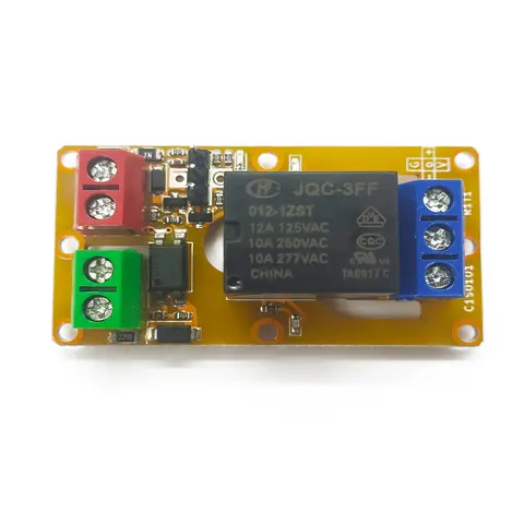
A1J0101 Economical Input Amplifier Module
Optocoupler-isolated input amplifier that turns a low-voltage signal into a 250V AC / 10A relay output.
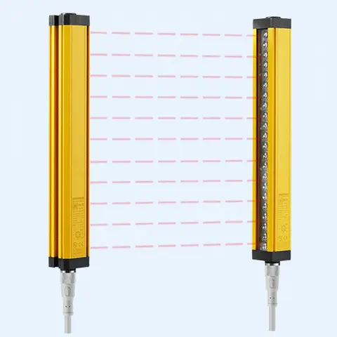
DCE Automation Safety Light Curtain
Compact through-beam safety light curtain in a 30 x 30 mm housing: 10/20/30/40 mm beam pitch, up to 72 beams, 0.3-3 m or 0.3-6 m sensing distance, NPN/PNP output. Catalogue-stated Type 4 design basis; confirm exact safety-document scope.
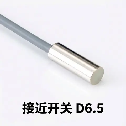
D6.5 Series Inductive Proximity Sensors (Ultra-Short 18mm / Y-Type / 35mm / 45mm)
6.5mm-diameter inductive proximity sensors for tight-clearance mounting where M8 sensors won't fit.
Related Products in LiDAR Scanners
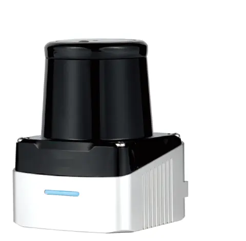
DLD-100D Single-Line TOF Scanning LiDAR
Single-line TOF scanning LiDAR with up to 100 m range, model-dependent 280°/360° coverage, and a 100 Hz / 0.32° DLD-100DP option.
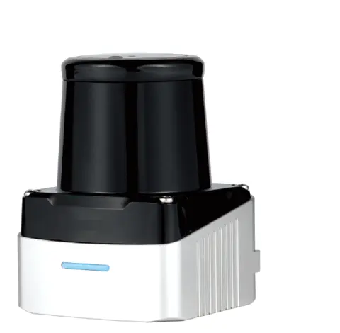
DLD-50D 2D TOF LiDAR for Navigation & Mapping (50 m)
50 m-range 2D TOF LiDAR for mobile robot navigation and mapping — ±20 mm repeatability, 280° FoV, Ethernet output.
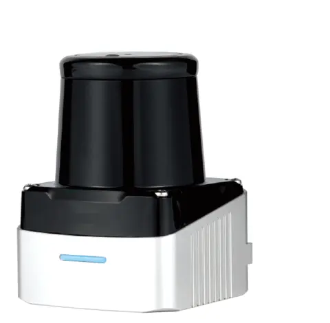
DLD-50G 2D Single-line LiDAR (Diffuse-remission Measuring Type)
2D single-line laser scanner measuring diffuse-remission distance off natural surfaces, no reflector needed.
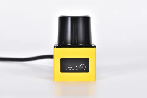
DLD05A3 2D TOF Obstacle-avoidance LiDAR (5 m)
2D TOF LiDAR with NPN/PNP switching outputs that wires like a photoelectric sensor — no protocol stack, no SDK.