
DCE Automation Safety Light Curtain
Compact through-beam safety light curtain in a 30 x 30 mm housing: 10/20/30/40 mm beam pitch, up to 72 beams, 0.3-3 m or 0.3-6 m sensing distance, NPN/PNP output. Catalogue-stated Type 4 design basis; confirm exact safety-document scope.
 🔍 Click to enlarge · 1/1
Technical Specifications
| Curtain Type | Through-beam (opposed mode) -- separate transmitter and receiver |
|---|---|
| Safety Design Basis | Catalogue-stated Type 4 / Category 4 (PLd), with IEC 61496-1/-3, EN 61496-3:2019, EN 13849-1:2015 and TUV/UL references. Exact rating, standard-part applicability and certificate scope require confirmation. GB/T19001-2016 idt ISO 9001:2015 is a quality-system reference, not certification of the ESPE safety function. |
| Beam Pitch | 10 / 20 / 30 / 40 mm |
| Detection Accuracy (min. detectable object) | 18 / 28 / 48 mm at 10/20/40 mm pitch respectively (= beam pitch + 8 mm). Not printed for 30 mm pitch in the catalog's parameter table. |
| Number of Beams | 12, 14 ... 70 (10 mm pitch); 6, 8 ... 72 (20 mm pitch); 4, 6 ... 72 (30 mm pitch); 4, 6 ... 72 (40 mm pitch) |
| Protected Height | Beam pitch x (number of beams - 1) |
| Sensing Distance | 0.3-3 m (model-code letter A) or 0.3-6 m (letter B), selectable by model code. Default detection distance is 0.3-3 m unless otherwise specified. |
| Response Time | <= 15 ms |
| Ambient Light Immunity | 10,000 lux (incidence angle >= 5 degrees) |
| Dimensions | 30 x 30 mm x L (L = transmitter / receiver length) |
| Enclosure Rating / Housing Material | IP65; aluminium alloy housing, end caps ABS-reinforced nylon |
| Controller | DQCA / DQCA2 |
| Supply Voltage / Current Consumption | DC 12/24 V or AC 110-220 V (relay-output version); <= 200 mA |
| Output | NPN / PNP type, sink current 500 mA, residual voltage < 1.5 V, with polarity, short-circuit and overload protection |
| Output State / Indicators | Catalogue wiring example: ON with beams clear (green receiver indicator); transmitter power indicator red, receiver blocked indicator red. Check the ordered NO/NC variant's own output-state table rather than applying this example to every configuration. |
| Light Source | Modulated infrared LED |
| Connection | Circular aviation connector with dedicated cable; transmitter 3-core, receiver 5-core (dual 7-core cabling for two-output-group models) |
| Ambient Light Tolerance (receiver face) | Incandescent light: 3,000 lux; sunlight: 10,000 lux |
| Operating Temperature | -10 to +40 degrees C (non-condensing); storage -25 to +55 degrees C |
| Ambient Humidity | Operating 35-85% RH; storage 35-95% RH |
Overview
The DCE is DAIDISIKE's compact through-beam (opposed-mode) safety light curtain: a separate transmitter and receiver, each housed in a 30 x 30 mm aluminium-alloy profile, project modulated infrared beams across a machine opening. Detection changes the output; stopping hazardous motion requires a connected and validated machine-safety circuit. The catalogue states a Type 4 / Category 4 (PLd) design basis, citing IEC 61496-1/-3, EN 61496-3:2019, EN 13849-1:2015, TUV/UL testing and the manufacturer's GB/T19001-2016 idt ISO 9001:2015 quality system. These references do not replace the exact model's applicable ESPE safety certificate, and quality-system certification does not certify the safety function. The catalogue's intended applications include automation equipment, presses, hydraulic and oil presses, shearing machines and automatic doors; verify suitability for the assessed machine before use.
DCE is configured across four beam pitches -- 10, 20, 30 and 40 mm -- with beam counts up to 72 depending on pitch, giving protected heights from under 100 mm up to 2840 mm (DCE72/40-2840, the largest catalog example). Sensing distance is selectable by model code between 0.3-3 m (code A) and 0.3-6 m (code B) -- a shorter range than the long-distance DQA series. Output is NPN or PNP transistor type (model-code letters A-D set NC/NO logic), wired through a circular aviation connector with dual 7-core cabling on two-output-group models, and the curtain pairs with the DQCA/DQCA2 controller. Its listed cross-section is 30 x 30 mm; use the selected models' current dimension drawings when comparing installation envelopes across series.
Features & Benefits
One series spans an OEM's full machine range
Beam pitches of 10, 20, 30 and 40 mm and beam counts up to 72 are specified within the DCE series, allowing model selection across different equipment openings. Pitch is the spacing between beam axes, not the minimum detectable object.
Protective heights up to 2840 mm
The largest listed model, DCE72/40-2840, provides a 2840 mm protective height, suitable for full-height opening protection on larger automated equipment.
Select by published minimum detectable object
The 10, 20 and 40 mm pitches have published minimum detectable objects of 18, 28 and 48 mm respectively. The 30 mm-pitch detection figure remains unconfirmed; do not calculate or assume it from pitch alone.
NPN/PNP selectable transistor output
Output signal type can be selected between NPN and PNP, allowing the same product to interface with control systems that expect either signal convention.
Compact 30 mm-pitch "Q" variants for small automation cells
At 30 mm beam pitch, models with 4-12 beams (DCE04/30-90Q through DCE12/30-330Q) are offered as Q-suffix variants with protective heights of 90-330 mm, sized for small automation cells. Their minimum detectable object must be confirmed before safety specification.
Dedicated end-mounting bracket supplied as standard
The DQCE-04 bracket, designed for two-end mounting, is supplied as standard with the DCE series; the general-purpose DQCA-01/02/03 brackets are also compatible accessories.
Applications
Models & Ordering Information
129 listed table entries across 4 beam-pitch options. Compare beam count and span, then confirm the complete ordering code. Beam pitch alone does not establish detection capability or suitability for personnel protection.
10 mm beam pitch; published minimum detectable object 18 mm, not 10 mm or 14 mm finger detection.
| Listed model entry | Beam pitch K (mm) | Number of beams N | Beam span H (mm) |
|---|---|---|---|
| DCE12/10-110 | 10 | 12 | 110 |
| DCE14/10-130 | 10 | 14 | 130 |
| DCE16/10-150 | 10 | 16 | 150 |
| DCE18/10-170 | 10 | 18 | 170 |
| DCE20/10-190 | 10 | 20 | 190 |
| DCE22/10-210 | 10 | 22 | 210 |
| DCE24/10-230 | 10 | 24 | 230 |
| DCE26/10-250 | 10 | 26 | 250 |
| DCE28/10-270 | 10 | 28 | 270 |
| DCE30/10-290 | 10 | 30 | 290 |
| DCE32/10-310 | 10 | 32 | 310 |
| DCE34/10-330 | 10 | 34 | 330 |
| DCE36/10-350 | 10 | 36 | 350 |
| DCE38/10-370 | 10 | 38 | 370 |
| DCE40/10-390 | 10 | 40 | 390 |
| DCE42/10-410 | 10 | 42 | 410 |
| DCE44/10-430 | 10 | 44 | 430 |
| DCE46/10-450 | 10 | 46 | 450 |
| DCE48/10-470 | 10 | 48 | 470 |
| DCE50/10-490 | 10 | 50 | 490 |
| DCE52/10-510 | 10 | 52 | 510 |
| DCE54/10-530 | 10 | 54 | 530 |
| DCE56/10-550 | 10 | 56 | 550 |
| DCE58/10-570 | 10 | 58 | 570 |
| DCE60/10-590 | 10 | 60 | 590 |
| DCE62/10-610 | 10 | 62 | 610 |
| DCE64/10-630 | 10 | 64 | 630 |
| DCE66/10-650 | 10 | 66 | 650 |
| DCE68/10-670 | 10 | 68 | 670 |
| DCE70/10-690 | 10 | 70 | 690 |
| Listed model entry | Beam pitch K (mm) | Number of beams N | Beam span H (mm) |
|---|---|---|---|
| DCE06/20-100 | 20 | 6 | 100 |
| DCE08/20-140 | 20 | 8 | 140 |
| DCE10/20-180 | 20 | 10 | 180 |
| DCE12/20-220 | 20 | 12 | 220 |
| DCE14/20-260 | 20 | 14 | 260 |
| DCE16/20-300 | 20 | 16 | 300 |
| DCE18/20-340 | 20 | 18 | 340 |
| DCE20/20-380 | 20 | 20 | 380 |
| DCE22/20-420 | 20 | 22 | 420 |
| DCE24/20-460 | 20 | 24 | 460 |
| DCE26/20-500 | 20 | 26 | 500 |
| DCE28/20-540 | 20 | 28 | 540 |
| DCE30/20-580 | 20 | 30 | 580 |
| DCE32/20-620 | 20 | 32 | 620 |
| DCE34/20-660 | 20 | 34 | 660 |
| DCE36/20-700 | 20 | 36 | 700 |
| DCE38/20-740 | 20 | 38 | 740 |
| DCE40/20-780 | 20 | 40 | 780 |
| DCE42/20-820 | 20 | 42 | 820 |
| DCE44/20-860 | 20 | 44 | 860 |
| DCE46/20-900 | 20 | 46 | 900 |
| DCE48/20-940 | 20 | 48 | 940 |
| DCE50/20-980 | 20 | 50 | 980 |
| DCE52/20-1020 | 20 | 52 | 1020 |
| DCE54/20-1060 | 20 | 54 | 1060 |
| DCE56/20-1100 | 20 | 56 | 1100 |
| DCE58/20-1140 | 20 | 58 | 1140 |
| DCE60/20-1180 | 20 | 60 | 1180 |
| DCE62/20-1220 | 20 | 62 | 1220 |
| DCE64/20-1260 | 20 | 64 | 1260 |
| DCE66/20-1300 | 20 | 66 | 1300 |
| DCE68/20-1340 | 20 | 68 | 1340 |
| DCE70/20-1380 | 20 | 70 | 1380 |
| DCE72/20-1420 | 20 | 72 | 1420 |
| Listed model entry | Beam pitch K (mm) | Number of beams N | Beam span H (mm) |
|---|---|---|---|
| DCE14/30-390 | 30 | 14 | 390 |
| DCE16/30-450 | 30 | 16 | 450 |
| DCE18/30-510 | 30 | 18 | 510 |
| DCE20/30-570 | 30 | 20 | 570 |
| DCE22/30-630 | 30 | 22 | 630 |
| DCE24/30-690 | 30 | 24 | 690 |
| DCE26/30-750 | 30 | 26 | 750 |
| DCE28/30-810 | 30 | 28 | 810 |
| DCE30/30-870 | 30 | 30 | 870 |
| DCE32/30-930 | 30 | 32 | 930 |
| DCE34/30-990 | 30 | 34 | 990 |
| DCE36/30-1050 | 30 | 36 | 1050 |
| DCE38/30-1110 | 30 | 38 | 1110 |
| DCE40/30-1170 | 30 | 40 | 1170 |
| DCE42/30-1230 | 30 | 42 | 1230 |
| DCE44/30-1290 | 30 | 44 | 1290 |
| DCE46/30-1350 | 30 | 46 | 1350 |
| DCE48/30-1410 | 30 | 48 | 1410 |
| DCE50/30-1470 | 30 | 50 | 1470 |
| DCE52/30-1530 | 30 | 52 | 1530 |
| DCE54/30-1590 | 30 | 54 | 1590 |
| DCE56/30-1650 | 30 | 56 | 1650 |
| DCE58/30-1710 | 30 | 58 | 1710 |
| DCE60/30-1770 | 30 | 60 | 1770 |
| DCE62/30-1830 | 30 | 62 | 1830 |
| DCE64/30-1890 | 30 | 64 | 1890 |
| DCE66/30-1950 | 30 | 66 | 1950 |
| DCE68/30-2010 | 30 | 68 | 2010 |
| DCE70/30-2070 | 30 | 70 | 2070 |
| DCE72/30-2130 | 30 | 72 | 2130 |
| Listed model entry | Beam pitch K (mm) | Number of beams N | Beam span H (mm) |
|---|---|---|---|
| DCE04/40-120 | 40 | 4 | 120 |
| DCE06/40-200 | 40 | 6 | 200 |
| DCE08/40-280 | 40 | 8 | 280 |
| DCE10/40-360 | 40 | 10 | 360 |
| DCE12/40-440 | 40 | 12 | 440 |
| DCE14/40-520 | 40 | 14 | 520 |
| DCE16/40-600 | 40 | 16 | 600 |
| DCE18/40-680 | 40 | 18 | 680 |
| DCE20/40-760 | 40 | 20 | 760 |
| DCE22/40-840 | 40 | 22 | 840 |
| DCE24/40-920 | 40 | 24 | 920 |
| DCE26/40-1000 | 40 | 26 | 1000 |
| DCE28/40-1080 | 40 | 28 | 1080 |
| DCE30/40-1160 | 40 | 30 | 1160 |
| DCE32/40-1240 | 40 | 32 | 1240 |
| DCE34/40-1320 | 40 | 34 | 1320 |
| DCE36/40-1400 | 40 | 36 | 1400 |
| DCE38/40-1480 | 40 | 38 | 1480 |
| DCE40/40-1560 | 40 | 40 | 1560 |
| DCE42/40-1640 | 40 | 42 | 1640 |
| DCE44/40-1720 | 40 | 44 | 1720 |
| DCE46/40-1800 | 40 | 46 | 1800 |
| DCE48/40-1880 | 40 | 48 | 1880 |
| DCE50/40-1960 | 40 | 50 | 1960 |
| DCE52/40-2040 | 40 | 52 | 2040 |
| DCE54/40-2120 | 40 | 54 | 2120 |
| DCE56/40-2200 | 40 | 56 | 2200 |
| DCE58/40-2280 | 40 | 58 | 2280 |
| DCE60/40-2360 | 40 | 60 | 2360 |
| DCE62/40-2440 | 40 | 62 | 2440 |
| DCE64/40-2520 | 40 | 64 | 2520 |
| DCE66/40-2600 | 40 | 66 | 2600 |
| DCE68/40-2680 | 40 | 68 | 2680 |
| DCE70/40-2760 | 40 | 70 | 2760 |
| DCE72/40-2840 | 40 | 72 | 2840 |
30 listed entries at 10 mm pitch · 129 across this table. Beam span is calculated as H = (N − 1) × K; it is not overall housing length or proof of detection capability. Some entries expand catalogue ranges. Confirm the complete ordering code and availability before ordering; inclusion is not a stock claim.
30 mm Pitch — Q Variants (Small Beam Count)
How to read the DCE model code
PDF & 3D CAD Downloads
Browse all downloadsDCE Safety Light Curtain Series Brochure
Confirm the document and CAD file match the exact ordered version before installation or mechanical design. Contact us if your model is not listed.
How to Select
- Naming: DCE + beam count + / + pitch (mm) + - + protective height (mm); Q suffix applies to small-beam-count models at 30 mm pitch.
- Select using the minimum detectable object, not pitch as a substitute: 10 mm pitch gives 18 mm detection capability (DCE12/10-110 to DCE70/10-690); 20 mm pitch gives 28 mm (DCE06/20-100 to DCE72/20-1420); 40 mm pitch gives 48 mm (DCE04/40-120 to DCE72/40-2840). The 30 mm-pitch standard and Q-suffix models require a confirmed detection figure before specification. No published DCE value establishes 14 mm finger detection.
- Match protective height to the actual guarded opening height using the model list; the maximum available is 2840 mm (DCE72/40-2840).
- Select NPN or PNP transistor output based on the signal convention of the on-site PLC/control cabinet.
- The DQCE-04 two-end mounting bracket is supplied as standard; general-purpose brackets DQCA-01, DQCA-02, and DQCA-03 are available as alternative mounting accessories.
📘 Need the full method? How to Choose a Safety Light Curtain · Type 2 vs Type 4 Safety Light Curtains
When NOT to specify the DCE — and what to use instead
You need an officially documented detection-accuracy figure at 30 mm pitch for a personnel risk assessment
Why not: The catalog's parameter table publishes detection accuracy only for the 10, 20 and 40 mm pitches (18, 28 and 48 mm respectively). 30 mm-pitch models appear in the full model listing and in the dimension/model-code diagrams, but no detection-accuracy figure is printed for that pitch in the parameter table.
Use instead: Confirm the 30 mm pitch detection-accuracy figure with us before specifying it for a safety application, or select the 20 mm or 40 mm pitch, whose detection-accuracy figures are documented.
True 14 mm finger-level detection, or a protected opening under 110 mm high
Why not: The finest DCE pitch is 10 mm, but its printed detection accuracy is 18 mm (pitch + 8 mm) -- a hand-level rather than strict finger-level figure. In addition, the catalog's 10 mm pitch model table starts at 12 beams (110 mm protected height); no smaller 10 mm-pitch model is listed.
Use instead: Request a series with documented 14 mm detection capability if that is required by the risk assessment. DQA/DQC may offer shorter protective heights, but their 10/14 mm pitches correspond to 18/22 mm minimum detectable objects and are not a substitute for a 14 mm detection requirement.
The transmitter-to-receiver span exceeds 6 m
Why not: DCE's model code offers only two sensing-distance steps -- 0.3-3 m (code A) and 0.3-6 m (code B) -- a shorter range than other series in the catalog.
Use instead: The DQA long-distance safety light curtain series, selectable up to 0.3-40 m by model code.
Washdown, high-pressure hosing, or wet/outdoor environments
Why not: The DCE housing is rated IP65 -- dust-tight and protected against low-pressure water jets, but not against high-pressure jetting or immersion.
Use instead: Evaluate a DQR configuration only after confirming the exact assembly against the actual water pressure, temperature, cleaning chemicals and connector/seal conditions. A waterproof family name or IP label alone does not establish high-pressure-washdown suitability.
The control cabinet needs a relay (volt-free) output, but the ordered code was NPN/PNP transistor output
Why not: The DCE model-code diagram defines only signal-output letters A/B/C/D (NPN/PNP, NC/NO); no relay ("J"-type) letter is shown there, even though the supply-voltage spec row separately lists an "AC 110-220V (relay output)" version -- so the relay-output ordering path is not fully documented on these pages.
Use instead: Confirm the relay-output ordering code with us before specifying, or select the DQA/DQC series where a relay (J) signal code is explicitly documented in the model-code table.
Ambient temperature outside -10 to +40 degrees C, or condensing conditions
Why not: The DCE operating range is -10 to +40 degrees C, non-condensing. Outside that band, or where the optical faces can condense or ice, detection is not guaranteed.
Use instead: A heated or sheltered enclosure that holds the curtain within spec, or confirm a wide-temperature option with us.
Specifications we do not publish yet
We only publish a figure once we are confident it is true. The items below are still being validated through further testing and real-world customer feedback, so for now we would rather leave them open than guess. If one of them matters to your design, ask us for the latest validated status.
- Detection accuracy (minimum detectable object) for the 30 mm beam pitch is not printed in the catalog's parameter table (only 10/20/40 mm figures -- 18/28/48 mm -- are given), even though 30 mm-pitch models are listed in the full model table.
- Relay (volt-free) output ordering code: the supply-voltage spec row mentions "AC110-220V (relay output)", implying a relay-output variant exists, but the DCE model-code diagram only defines signal letters A/B/C/D (NPN/PNP, NC/NO) with no relay/J letter shown.
- The meaning of the "Q" suffix on the 30 mm-pitch models DCE04/30-90Q through DCE12/30-330Q -- only these five models carry the suffix; the rest of the 30 mm range and all 10/20/40 mm models do not.
- The "DCEL" designation referenced in the accessory selection guide (the DQCE-04 bracket is listed as being "for DCEL two-end mounting") does not otherwise appear on the DCE pages; its relationship to the DCE series is not documented here.
- TUV and UL certificate numbers and their exact scope (which DCE pitch/beam-count configurations are covered). Certification documents are available on request.
- PFHd, MTTFd and DCavg figures needed to integrate DCE into a full ISO 13849-1 machine-level calculation -- the catalog states Category 4 PLd but does not publish these figures.
- Muting and fixed/floating blanking function availability and configuration are not mentioned on the DCE pages.
- Cable length options and the full aviation-connector pinout beyond the stated 3-core (transmitter) / 5-core (receiver) core count.
Frequently Asked Questions
What beam pitches and detection capabilities does the DCE series offer?
What is the maximum protective height in the DCE series?
What is the maximum number of beams available?
Does the DCE series support both NPN and PNP output?
What does the "Q" suffix mean in model numbers like DCE04/30-90Q?
What mounting accessories are available for the DCE series?
Who is the DCE series designed for?
Related Categories and Example Products
Explore other functions that may be needed in a machine or line. The products below are category examples, not pre-validated electrical or safety combinations. Confirm each interface and application separately: Safety Relays · Safety Door Locks & Switches · Press & Press Brake Protection
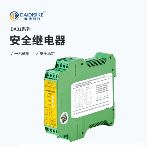
DA31 Emergency-Stop Safety Relay Module
Ultra-slim 22.6 mm Category 4/PL e/SIL 3 safety relay with dual-channel PNP/NPN input and a solid-state status output.
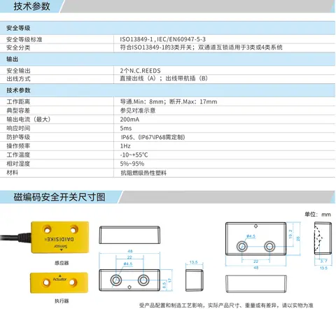
DX-C1 Magnetic Coded Safety Switch
Non-contact coded-magnet safety switch with 17 mm sensing range and high misalignment tolerance for guard doors.
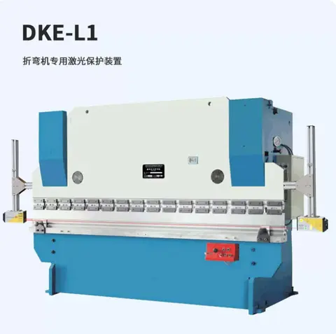
DKE-L3 Press Brake Laser Protection
Ram-mounted laser guarding that tracks the punch tip on press brakes and shears without blocking hand-fed work.
Related Products in Safety Light Curtains
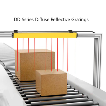
DD / DDOF Single-Sided Area Light Curtain
One housing, no far-side receiver: order DD for diffuse sensing to 2000 mm, or DDOF for per-beam TOF ranging to 4000 mm with zero dead zone and one-key distance teaching. 48 standard models, 4-50 beams.
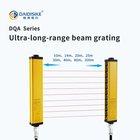
DQA Long-distance Safety Light Curtain
Long-range through-beam safety light curtain for large presses, hydraulic and shearing machines: a transmitter/receiver pair spanning up to 40 m, in 8 beam pitches from 10 to 200 mm, with NPN, PNP or relay output and a selectable single- or dual-output signal. Designed to the Type 4 architecture of IEC 61496 and Category 4 of ISO 13849-1.
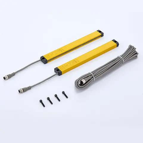
DQB Ultra-thin (Side-emitting) Safety Light Curtain
Ultra-thin side-emitting safety light curtain with a 15 x 30 mm cross-section for gaps too narrow for standard units.
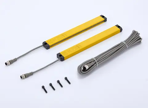
DQBT Ultra-thin Optical-sync Safety Light Curtain
Ultra-thin safety light curtain with optical sync between emitter and receiver — no interconnecting sync cable — in 10/20/40 mm beam pitch, transistor NPN/PNP output, 0.3-3 m detection distance.