
DX-C1 Magnetic Coded Safety Switch
Non-contact coded-magnet safety switch with 17 mm sensing range and high misalignment tolerance for guard doors.
▶ Watch it in action: Safety Light Curtain + Guard-Locking Door Switch Interlock — Wiring Demo
 🔍 Click to enlarge · 1/4
Technical Specifications
| Output type | Magnetic reed-type contact: 2C = two NC contacts / 1C1O = one NC + one NO contact / 2O = two NO contacts |
|---|---|
| Connection type | A = direct 2 m pre-wired cable / B = quick-disconnect (aviation-style) connector |
| Sensing distance | Up to 17 mm in the Z direction and Y direction |
| Ingress protection | IP65 (IP67/IP68 available on custom order) |
| Safety design level | ISO 13849-1, designed for use in circuits up to PLe / Cat. 4 |
| Working principle | Multiple magnetically sensitive elements triggered in a defined sequence; multiple switches can be connected in series |
Overview
DX-C1 is a two-part non-contact safety switch consisting of a sensor head and a coded-magnet actuator, mounted on the fixed frame and the movable guard respectively. Inside the sensor, multiple magnetically sensitive elements must be triggered in a defined sequence for the switch to operate — a plain magnet placed against the sensor will not actuate it.
It outputs through contacts in three configurations (2 NC / 1 NC + 1 NO / 2 NO) and is intended for machine builders and panel integrators who need to monitor the position of hinged doors, sliding guards, or removable guard panels as part of a machine safety circuit, typically feeding a safety relay or safety PLC.
Features & Benefits
Coded-magnet actuation resists simple defeat
Multiple magnetically sensitive elements inside the switch must be triggered in a defined sequence before it will operate; a single ordinary magnet placed against the housing does not actuate it, which is the key difference from a plain reed-type door magnet.
Large 17 mm sensing range with high misalignment tolerance
Sensing distance up to 17 mm in both the Z and Y directions gives generous installation and operating tolerance, so the switch continues to actuate reliably even when a guard door has sagged, the track has worn, or the panel is slightly out of alignment.
Three contact output configurations for flexible circuit design
Available as 2 NC (two normally closed), 1 NC + 1 NO, or 2 NO, so integrators can wire dual-NC channels straight into a safety relay while using an NO contact for status/PLC indication, matched to the specific safety circuit design.
Designed for use in circuits up to PLe / Cat. 4 per ISO 13849-1
The switch is CE marked and designed for use in safety circuits rated up to Performance Level e, Category 4 under ISO 13849-1, suitable for high-demand guard interlocking applications when combined with an appropriately rated safety relay or logic solver.
Series connection reduces wiring for multi-door lines
Multiple DX-C1 switches can be connected in series, allowing several guard doors on a line to be monitored through a single safety relay input, cutting the number of I/O points and cable runs.
Two connection styles to match maintenance workflow
Available with a 2 m pre-wired cable (A version) or a quick-disconnect connector (B version), so a failed switch on the B version can be swapped without re-wiring the panel.
Sealed, flame-retardant IP65 housing
The switch body is molded from flame-retardant thermoplastic and rated IP65 as standard, with IP67/IP68 available on request for wash-down or heavier contamination environments; the non-contact sensing design has no exposed mechanical contacts or plug apertures where dirt can accumulate on the sensing face.
Applications
Models & Ordering Information
A version — 2 m pre-wired cable
B version — quick-disconnect connector
How to Select
- Choose 2C (two NC contacts) when both channels need to be normally closed for direct connection to the dual-channel monitoring input of a safety relay — the standard configuration for a safety circuit.
- Choose 1C1O (one NC + one NO) when one normally closed channel feeds the safety circuit and the normally open channel is used for door-position status feedback to a PLC or controller.
- Choose 2O (two NO contacts) for non-safety position detection/status indication applications; whether it can be used in a safety circuit depends on the specific safety-level requirement and is not separately specified by the manufacturer.
- Choose the A version (2 m pre-wired cable) for fixed installations that are not frequently removed.
- Choose the B version (quick-disconnect connector) when fast switch replacement with minimal re-wiring and downtime is needed.
- The standard IP65 rating covers general industrial environments; for wash-down, dust, or higher-moisture environments, request the custom IP67/IP68 option.
- If the guard door sags slightly, vibrates, or has installation misalignment, the 17 mm (Z/Y direction) sensing distance and high misalignment tolerance reduce the risk of nuisance stops without extra mechanical fine-adjustment.
- For single-point position monitoring, one switch paired with a safety relay is sufficient; for multi-door lines, multiple DX-C1 switches can be connected in series to share a single safety relay input.
📘 Need the full method? How to Choose a Safety Door Switch / Interlock
When NOT to specify the DX-C1 — and what to use instead
The guard must remain physically locked shut while the machine coasts down or retains stored energy after the stop command.
Why not: DX-C1 is a position-monitoring switch only -- it has no locking mechanism, so it cannot hold the door closed once it is unlatched.
Use instead: DX-D6 guard-locking safety-door switch, or a DX-W2/DX-W3/DX-W5 solenoid door lock
Operators are likely to attempt bypass with a substitute actuator and the risk assessment calls for the highest coding/tamper-resistance level.
Why not: DX-C1's coded-magnet actuation resists a plain magnet, but the published spec does not classify it to an ISO 14119 coding level (Low/High), unlike the RFID-coded DX-R1, which is explicitly offered in a uniquely-coded (D, High level coded) version.
Use instead: DX-R1 non-contact safety switch, D (uniquely coded) version
The safety function must be formally validated (SISTEMA/PFHd calculation) or a specific certificate number cited in the machine's technical file.
Why not: DX-C1 is only described as designed for use in circuits up to PLe/Cat.4 under ISO 13849-1; no PFHd/B10d/MTTFd figures or certificate number are published, and certification documents are supplied only on request.
Use instead: Request the certification package from the factory before specifying, and validate the complete circuit together with a DA31 or DQSRN safety relay
The guard door is exposed to washdown, coolant spray, or heavy dust beyond general industrial conditions.
Why not: Standard DX-C1 units are rated IP65; IP67/IP68 is only available as a custom order, not a stocked catalog option.
Use instead: Order the custom IP67/IP68 DX-C1 variant, or specify the standard-IP67 DX-D2/DX-D3 mechanical switch
The circuit needs a documented electrical contact rating (voltage/current) or a published mechanical/electrical cycle life to size the downstream relay or estimate service life.
Why not: DX-C1's datasheet gives sensing distance, output configuration, and IP rating, but does not publish a contact voltage/current rating or a mechanical/electrical operations count.
Use instead: DX-D2/DX-D3, which publish Ui 400V/Ith 8A/Ue AC400V/Ie 2A ratings and a 1,000,000/300,000 mechanical/electrical life
Specifications we do not publish yet
We only publish a figure once we are confident it is true. The items below are still being validated through further testing and real-world customer feedback, so for now we would rather leave them open than guess. If one of them matters to your design, ask us for the latest validated status.
- Sensor operating voltage and power/current draw
- Response (switching) time
- Overall housing dimensions and mounting-hole pattern
- PFHd / B10d / MTTFd reliability figures
- Certificate number and scope for the CE / ISO 13849-1 design basis
- Electrical contact rating (voltage/current) of the reed-type contacts
- Approach speed / minimum safety-distance guidance for ISO 13855 calculations
Frequently Asked Questions
What makes DX-C1 different from a simple magnetic door sensor?
What is the maximum sensing distance of DX-C1?
What contact output configurations are available?
Can multiple DX-C1 switches be wired together?
What safety performance level is DX-C1 designed for?
What ingress protection rating does DX-C1 have?
What connection options are available — cable or connector?
Does DX-C1 lock the guard door, or only monitor its position?
How many DX-C1 model variants are offered?
What housing material is DX-C1 made from?
Is DX-C1 certified to a specific safety standard?
Related Categories and Example Products
Explore other functions that may be needed in a machine or line. The products below are category examples, not pre-validated electrical or safety combinations. Confirm each interface and application separately: Safety Relays · Safety Light Curtains · Safety Mats
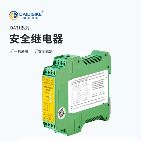
DA31 Emergency-Stop Safety Relay Module
Ultra-slim 22.6 mm Category 4/PL e/SIL 3 safety relay with dual-channel PNP/NPN input and a solid-state status output.
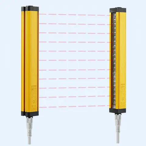
DCE Automation Safety Light Curtain
Compact through-beam safety light curtain in a 30 x 30 mm housing: 10/20/30/40 mm beam pitch, up to 72 beams, 0.3-3 m or 0.3-6 m sensing distance, NPN/PNP output. Catalogue-stated Type 4 design basis; confirm exact safety-document scope.
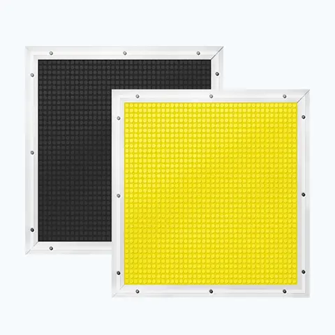
JT14 Safety Mat (Economical)
Economical pressure-sensitive safety mat with volt-free N.O. output for large-area or custom-shape floor guarding.
Related Products in Safety Door Locks & Switches
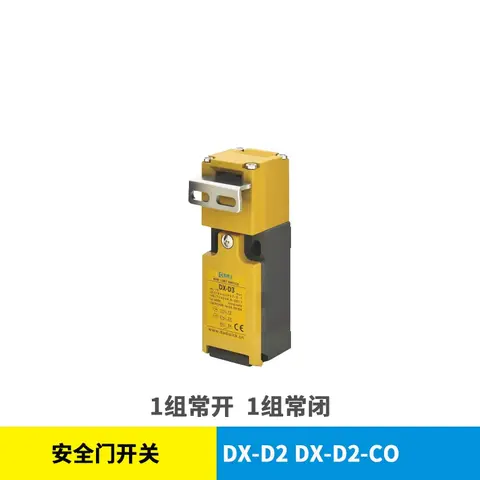
DX-D2 & DX-D3 Safety Door Switch
Mechanical NC/NO safety interlock switch, IP67, 1,000,000-cycle mechanical life, no locking function.
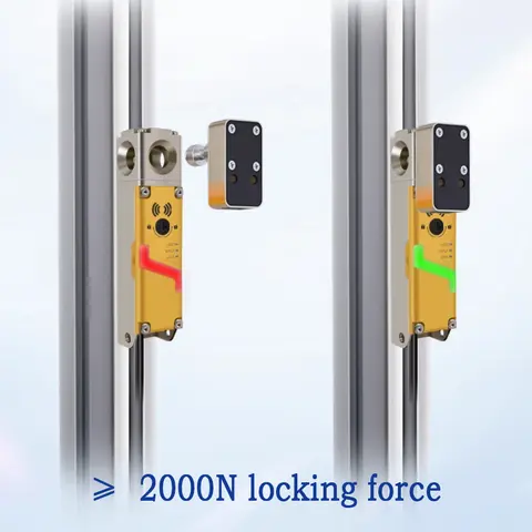
DX-D6 Guard Locking Safety-Door Switch
Guard locking safety-door switch: 2000 N holding force, redundant dual outputs, RFID-coded actuators.
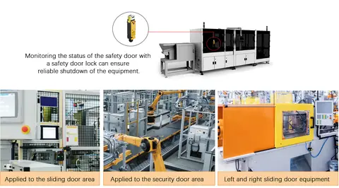
DX-K Series Safety Door Lock Operation Keys
11-model range of fixed and adjustable operation keys for DX-W2/W3/W5 and DX-D2/D3 safety door interlock switches.
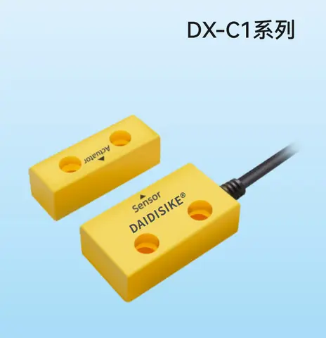
DX-R1 Non-contact Safety Switch (RFID Coded)
Non-contact RFID-coded safety switch, dual-channel PLe/Type 4 output, 0-10mm switch-on, cascadable, 8 NPN/PNP models.