
DX-R1 Non-contact Safety Switch (RFID Coded)
Non-contact RFID-coded safety switch, dual-channel PLe/Type 4 output, 0-10mm switch-on, cascadable, 8 NPN/PNP models.
▶ Watch it in action: Safety Light Curtain + Guard-Locking Door Switch Interlock — Wiring Demo
 🔍 Click to enlarge · 1/9
Technical Specifications
| Output Method | Dual-channel transistor output, N=NPN / P=PNP |
|---|---|
| Safety Output Current | 150mA |
| Auxiliary Output Current | 50mA |
| Coding Method | S=Universal coded (Low level coded, ISO 14119) / D=Uniquely coded (High level coded) |
| Detection Distance (Horizontal) | Switch-on 0-10mm / Switch-off >25mm |
| Detection Distance (Vertical) | Switch-on 0-6mm / Switch-off >15mm |
| Operating Voltage | 24VDC |
| Working Current | 30mA |
| Response Time | 60ms |
| Operating Frequency | 1Hz |
| Ingress Protection | IP65 (IP67/IP68 available on request) |
| Safety Rating | Type 4 (ISO 14119); PLe |
| Cable | 2m standard |
Overview
The DX-R1 is a non-contact RFID-coded safety switch consisting of a sensor (receiver) and a matching actuator (transponder), mounted on a movable guard door and its fixed frame respectively. Unlike mechanical interlock switches that require precise physical alignment and a plunger or key insertion, the DX-R1 detects the actuator's presence through RFID coding without any mechanical contact, switching on when the actuator is within 0-10mm (horizontal) or 0-6mm (vertical) of the sensor face.
It is intended for machine builders and end users who need to monitor -- not lock -- the closed/open state of hinged, sliding, or removable guard doors on machine tools, robot cells, packaging lines, and food/pharma equipment, with the output wired into a safety relay or safety PLC to achieve a defined Performance Level. The DX-R1 provides dual-channel solid-state safety outputs (150mA), two ISO 14119 coding levels (universal or unique), and is available in 8 complete-set catalog models covering 4-wire and 6-wire cascade wiring in both NPN and PNP output.
Features & Benefits
Non-contact Detection Tolerates Real-World Door Misalignment
Horizontal assured switch-on 0-10mm / switch-off >25mm, vertical switch-on 0-6mm / switch-off >15mm. No mechanical wear from repeated key insertion, and no false trips from minor door sag, hinge play, or frame deformation that would jam a mechanical plunger switch.
Two ISO 14119 Coding Levels Match Tamper-Resistance to Risk Level
Universal coded (S, low level coded) works with any actuator in the same series for fast commissioning; uniquely coded (D, high level coded) only responds to its paired actuator, closing the loophole where an operator swaps in a spare actuator to defeat the interlock.
Dual-Channel Solid-State Safety Output Supports PLe / Type 4 Interlocking
Two independent transistor safety output channels (150mA) provide redundancy so a single-channel fault does not silently defeat the interlock; combined with a suitable safety relay this supports Performance Level e per ISO 13849-1 and Type 4 interlocking device classification per ISO 14119.
NPN and PNP Versions Cover Both Sinking and Sourcing Architectures
All 8 catalog models come in matched N (NPN) / P (PNP) pairs, so the correct output polarity for a given safety relay or PLC input card is a straightforward model selection rather than a rewiring problem.
6-Wire E-Type Version Supports Series (Cascade) Wiring of Multiple Switches
On the E-type, the first unit's safety input terminals connect to 0V, its safety output feeds the next unit's safety input, and so on down the chain -- multiple guard doors on one line can be monitored through a single safety relay input pair, reducing both cable runs and safety-relay input channels needed.
Auxiliary Output Gives Per-Door Status Independent of the Safety Chain
A separate 50mA auxiliary/diagnostic output can be wired to a standard PLC input to indicate this specific door's open/closed state -- useful on an HMI to pinpoint which door in a cascaded chain is open, without walking the line.
60ms Response Time and 1Hz Operating Frequency Suit Production-Line Stop Requirements
Fast enough response to feed into a machine's safe-stop timing budget on doors that are opened/closed at normal operator pace.
IP65-Rated Flame-Retardant Housing, IP67/IP68 Available on Request
Suitable for standard industrial environments as shipped, with higher ingress protection available for washdown or wet-process applications via customization.
Applications
Models & Ordering Information
Universal Coded (S), 4-wire (F-type)
Universal Coded (S), 6-wire Cascade (E-type)
Uniquely Coded (D), 4-wire (F-type)
Uniquely Coded (D), 6-wire Cascade (E-type)
PDF & 3D CAD Downloads
Browse all downloadsDX-R1 Non-contact Safety Door Switch User Manual
Confirm the document and CAD file match the exact ordered version before installation or mechanical design. Contact us if your model is not listed.
How to Select
- Model naming: DX-R1-[E/F][N/P]-[S/D]-[P1/P2/P3].
- Choose F (4-wire, direct-out 2m cable, no cascading) for a single, standalone guard door.
- Choose E (6-wire, direct-out 2m cable, supports series/cascade wiring) when multiple guard doors need to be monitored through one safety relay input.
- Choose N (NPN, sinking output) or P (PNP, sourcing output) to match your safety relay's/PLC's input wiring convention; confirm before ordering, as the two are not interchangeable without external conversion.
- Choose S (universal coded, Low level coded) for simpler commissioning and spare-parts logistics where defeat-resistance is a lower priority.
- Choose D (uniquely coded, High level coded) where tamper/bypass risk assessment calls for higher defeat-resistance -- the sensor only responds to its paired actuator.
- Choose the package option: P1 = complete set (sensor + actuator, the standard order for a new installation and the option covered by the 8 catalog models); P2 = actuator only (for adding doors to an existing cascade or replacing a damaged actuator); P3 = sensor only (for replacing a damaged sensor without reordering the actuator).
- Assured switch-on/switch-off distances (10mm/25mm horizontal, 6mm/15mm vertical) and IP65 rating are fixed on the standard catalog models; IP67/IP68 protection and non-standard cable lengths are available as custom orders -- specify at time of inquiry.
📘 Need the full method? How to Choose a Safety Door Switch / Interlock
When NOT to specify the DX-R1 — and what to use instead
The guard door must be physically held closed, not just monitored.
Why not: DX-R1 is a position-monitoring switch -- it detects open/closed state but does not mechanically lock the door.
Use instead: DX-D6 guard-locking switch, or DX-R1 paired with the DXL safety door bolt
Risk assessment calls for the highest coding level but the S (universal-coded) version is chosen for convenience.
Why not: S is Low level coded per ISO 14119 and will trigger with any actuator in the series, which is easier to commission but does not resist a substitute actuator the way the D (High level, uniquely coded) version does.
Use instead: DX-R1, D (uniquely coded) version
The guard door sags, vibrates, or is installed with more misalignment than roughly 10mm horizontal / 6mm vertical.
Why not: DX-R1's assured switch-on distance is only 0-10mm horizontal and 0-6mm vertical, smaller than the coded-magnet DX-C1's 17mm sensing range.
Use instead: DX-C1 magnetic coded safety switch, which tolerates larger misalignment
The installation is exposed to washdown or wet-process conditions beyond general industrial use, and a custom IP67/68 unit was not ordered.
Why not: Standard DX-R1 units are IP65; IP67/68 protection is available only as a custom order.
Use instead: Order the custom IP67/68 DX-R1 variant, or specify the standard-IP67 DX-D2/DX-D3 mechanical switch
The project needs a published PFHd or an independently issued certificate number rather than a design-basis statement.
Why not: DX-R1 is described as supporting PLe / Type 4 per ISO 14119 as a design basis when paired with a suitable safety relay; no PFHd/B10d/MTTFd or certificate number is published, and documents are supplied only on request.
Use instead: Request the certification package from the factory and validate the full circuit with a DA31 or DQSRN safety relay
Specifications we do not publish yet
We only publish a figure once we are confident it is true. The items below are still being validated through further testing and real-world customer feedback, so for now we would rather leave them open than guess. If one of them matters to your design, ask us for the latest validated status.
- PFHd / B10d / MTTFd reliability figures
- Certificate number and scope for the PLe / Type 4 / ISO 14119 design basis
- Overall housing dimensions and material
- Operating temperature range
- Connector/cable options beyond the standard 2m direct-out cable
- Mounting hole spacing/pattern
Frequently Asked Questions
What is the difference between the F-type and E-type DX-R1?
What is the difference between universal coded (S) and uniquely coded (D) versions?
What is the detection (assured switching) distance of the DX-R1?
What safety performance level can the DX-R1 support?
Does the DX-R1 lock the guard door shut?
How do I wire multiple DX-R1 switches together?
What is the auxiliary output used for?
Is NPN or PNP output available?
What is the IP rating, and can it be upgraded?
What cable length does the switch ship with?
Can the DX-R1 be certified to CE, UL, or other standards?
Related Categories and Example Products
Explore other functions that may be needed in a machine or line. The products below are category examples, not pre-validated electrical or safety combinations. Confirm each interface and application separately: Safety Relays · Safety Light Curtains · Safety Mats
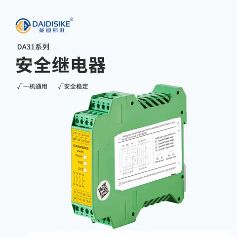
DA31 Emergency-Stop Safety Relay Module
Ultra-slim 22.6 mm Category 4/PL e/SIL 3 safety relay with dual-channel PNP/NPN input and a solid-state status output.
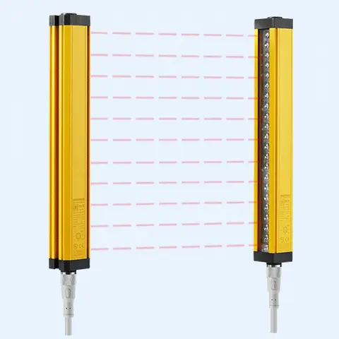
DCE Automation Safety Light Curtain
Compact through-beam safety light curtain in a 30 x 30 mm housing: 10/20/30/40 mm beam pitch, up to 72 beams, 0.3-3 m or 0.3-6 m sensing distance, NPN/PNP output. Catalogue-stated Type 4 design basis; confirm exact safety-document scope.
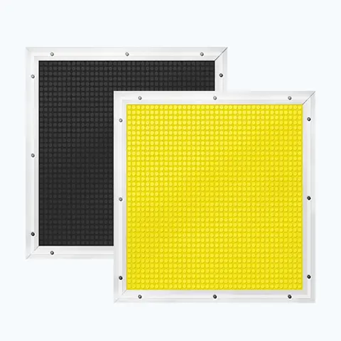
JT14 Safety Mat (Economical)
Economical pressure-sensitive safety mat with volt-free N.O. output for large-area or custom-shape floor guarding.
Related Products in Safety Door Locks & Switches
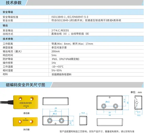
DX-C1 Magnetic Coded Safety Switch
Non-contact coded-magnet safety switch with 17 mm sensing range and high misalignment tolerance for guard doors.
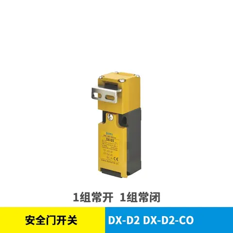
DX-D2 & DX-D3 Safety Door Switch
Mechanical NC/NO safety interlock switch, IP67, 1,000,000-cycle mechanical life, no locking function.
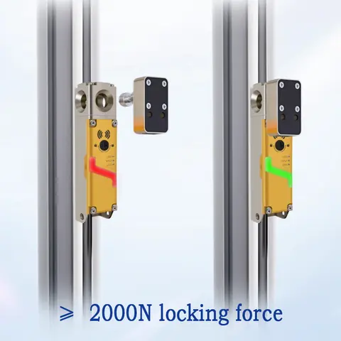
DX-D6 Guard Locking Safety-Door Switch
Guard locking safety-door switch: 2000 N holding force, redundant dual outputs, RFID-coded actuators.
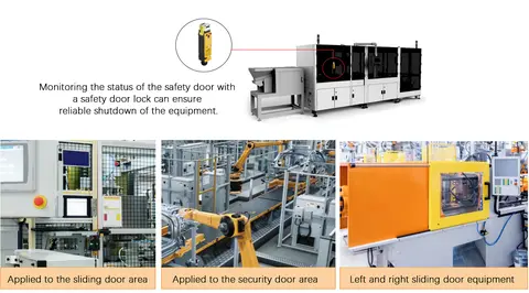
DX-K Series Safety Door Lock Operation Keys
11-model range of fixed and adjustable operation keys for DX-W2/W3/W5 and DX-D2/D3 safety door interlock switches.