
B2J0701 Ethernet to RS-485 MODBUS-TCP Gateway Module
Economical Ethernet-to-RS-485 gateway that converts MODBUS-TCP to MODBUS-RTU, offers transparent serial tunnelling, works as TCP server or cloud-connecting client, and drops a whole RS-485 field bus onto your LAN for the price of a sensor.
 🔍 Click to enlarge · 1/5
Technical Specifications
| Product Type | Economical Ethernet to RS-485 gateway module (MODBUS-TCP/RTU gateway + transparent serial server) |
|---|---|
| Ethernet Port | RJ45, 10Base-T, with magnetics; silver-shielded jack |
| Serial Port | RS-485 half-duplex (A/B differential pair on screw terminals) |
| Serial Parameters | All common baud rate / parity / stop-bit combinations; factory default 9600, 8 data bits, even parity, 1 stop bit |
| Protocol Conversion | MODBUS-TCP to MODBUS-RTU gateway mode with request-response management and frame-timeout handling |
| Transparent Mode | Bidirectional serial tunnelling; 4 KiB receive + 4 KiB transmit buffers; escape-sequence pass-through for local commands; basic transport encryption option |
| Network Roles | TCP server (host connects to module) or TCP client (module connects out to host/cloud server); one TCP connection at a time, commands always initiated by the host |
| IP Addressing | Static IP or DHCP; defaults: IP 192.168.8.8, mask 255.255.255.0, gateway 192.168.8.1, device port 502 |
| Payload Wrapping | Raw data (best legacy compatibility) or ASCII AT protocol (AT+DAT= with hex payload) |
| RS-485 Default Address | Host address 0xF7 (automatically 0x01 while USB is attached) |
| Configuration | Via mini-USB (enumerates as virtual serial port; priority when attached) or via the Ethernet port; serial RS-485 port cannot configure the device |
| Firmware Update | Over USB with the supplied software (not available over Ethernet); interrupted updates recover on next attempt |
| USB Pass-Through | Commands addressed to other MODBUS addresses relay to the RS-485 bus — one USB cable commissions the gateway and every slave behind it |
| GPIO | 4 multipurpose input/output lines, 3.3 V CMOS, input threshold approx. 3 V, push-pull outputs; unprotected and NOT 5 V tolerant |
| Analog Inputs | 4 channels shared with the GPIO lines (registers 0x0020-0x0023); 1 mV per LSB, about 10 bits effective, typical accuracy 3% |
| Sensor Supply | 5 V / 50 mA total on two internal auxiliary connectors (unprotected — keep total sensor current below 50 mA) |
| Auxiliary Access | GPIO, analog and sensor-supply lines sit inside the enclosure; open the case and use the supplied leads to bring them out |
| Indicators | Power LED (green) and RS-485 communication LED (red) |
| Supply Versions | 5 V (4.8-5.2), 9 V (8.5-11), 12 V (11-14), 24 V (20-28) DC; custom voltages for batch orders |
| Supply Current / Ripple | Under 50 mA (approx. 40 mA typical); ripple under 1 V peak-peak |
| Protection | Reverse-polarity protection, 500 mA / 30 V resettable fuse, ESD / EFT / surge immunity per IEC 61000-6-1:2016 light-industrial levels |
| Communication Port Withstand | RS-485 terminals 0-5 V working, 50 V absolute maximum |
| GPIO Withstand | 0-3.3 V working AND absolute maximum — no overvoltage margin; treat as logic-level only |
| Operating / Storage Temperature | -20 to +60 C operating; -40 to +85 C storage |
| Dimensions | PCB 55 x 30 mm, mounting holes 49 / 24.5 mm, terminal pitch 5.08 mm; enclosure 60.5 x 35.5 x 22 mm; DIN-rail bracket version for 35 mm rail |
| Interface Hardware | 4 screw terminals (power +/-, RS-485 A/B), RJ45, mini-USB, 2 internal auxiliary connectors |
| Intended Environment | Light-industrial per IEC 61000-6-1; for harsh-EMC sites use a filtered/EFT-rated supply and keep the supply lead under 3 m |
Overview
The B2J0701 is an economical Ethernet-to-RS-485 gateway module — a compact serial device server that connects a half-duplex RS-485 field bus to a 10Base-T Ethernet network. Built around a dedicated control IC on the same proven 55 x 30 mm board format as our other serial modules, it does the one job that every modern acquisition and control project eventually needs: making MODBUS-RTU devices that only speak RS-485 reachable from PCs, PLCs, SCADA hosts and cloud platforms that speak MODBUS-TCP over the network.
Two conversion modes cover practically every integration case. In MODBUS gateway mode, the module receives MODBUS-TCP frames on the network side, converts any frame addressed to a downstream device into an equivalent MODBUS-RTU frame on the RS-485 side, forwards the reply back over TCP, and manages request-response pacing with a frame-timeout mechanism so a silent slave never hangs the bus. In transparent mode, TCP payload data is tunnelled to the RS-485 port as-is — with 4 KiB buffers in each direction and a basic transport-encryption option — which keeps legacy serial protocols and third-party instruments working unchanged over the network.
The network side is equally flexible. The module can act as a TCP server on the LAN — the classic MODBUS-TCP topology where the host connects in to the module's IP (default 192.168.8.8, port 502, static or DHCP) — or it can reverse the roles and act as a TCP client that dials out to your host or cloud server. Client mode is the practical answer for wide-area installations where modules sit behind NAT routers with unknown addresses: each B2J0701 phones home, so the server never needs to find it. Data can be carried raw for maximum compatibility with legacy industrial software, or wrapped in a simple ASCII AT protocol (AT+DAT=...) that makes scripted access from network tools trivial.
Configuration is refreshingly practical: plug in the mini-USB cable and the module enumerates as a virtual serial port with a fixed MODBUS address, ready for the supplied configuration software — which can also pass commands through to every RTU slave on the attached bus, making the USB port a commissioning tool for the whole network. Configuration over the Ethernet port is supported too, and firmware updates load over USB. Inside the enclosure, four 3.3 V multipurpose GPIO lines, four shared 1 mV-resolution analog inputs and a 5 V / 50 mA sensor supply are available on auxiliary connectors for light auxiliary duties. Supply versions cover 5, 9, 12 and 24 V DC at under 50 mA, with reverse-polarity, resettable-fuse and ESD protection as standard.
Features & Benefits
Your Whole RS-485 Bus, On the Network
One B2J0701 at the head of a MODBUS-RTU segment makes every slave on it — I/O modules, meters, drives, sensors — addressable from any MODBUS-TCP host on the LAN. No PC-side serial cards, no USB dongles per workstation, no cable-length battles: just an IP address and port 502.
Gateway Mode and Transparent Mode in One Device
MODBUS shops get true TCP-to-RTU protocol conversion with managed request-response timing. Everyone else gets a transparent serial tunnel with 4 KiB buffering that carries any legacy protocol unchanged. You choose the mode per installation — the hardware is the same.
TCP Client Mode Beats the NAT Problem
Modules deployed across sites sit behind routers with private, changing addresses — a server-only device would be unreachable. The B2J0701 can connect outward to your central host or cloud server, so remote RS-485 networks report in from anywhere with an internet connection, no port-forwarding required.
USB Commissioning for the Entire Bus
Plug in the mini-USB lead and the module becomes a virtual COM port: configure the gateway, update firmware, and — because commands to other addresses pass straight through to the RS-485 side — talk to every RTU slave on the segment from the same cable. One laptop port commissions the whole network.
Raw Data or AT Protocol — Integrator's Choice
Raw mode keeps byte-for-byte compatibility with the legacy SCADA and instrument software the plant already runs. AT mode (AT+DAT= with hex payload) lets scripts and network debug tools exchange serial data in plain ASCII without building binary frames.
Static IP or DHCP, Server or Client
Fixed addressing for controlled plant networks, DHCP for drop-in deployment, server mode for classic topologies, client mode for wide-area ones — four combinations that cover LAN benches to nationwide device fleets with the same part number.
Bonus I/O Inside the Case
Four 3.3 V CMOS multipurpose input/output lines, four shared analog inputs read over MODBUS at 1 mV resolution, and a 5 V / 50 mA sensor supply live on internal auxiliary connectors — enough to watch a door contact or power a small sensor head at the gateway location without another module.
The Family Form Factor Your Panels Already Know
The B2J0701 PCB is 55 x 30 mm with 49 / 24.5 mm mounting holes. Specify its optional enclosure or DIN-rail bracket separately. Check the drawings and supply version of every connected B2J or D3J module; a shared communications bus does not mean identical dimensions, brackets or power supplies.
Applications
Models & Ordering Information
B2J0701 Series — Ethernet to RS-485 gateway
How to Select
- Bare-board supply, enclosure and DIN-rail mounting are ordering options for this B2J/E4J module. Specify what is included on the quotation; do not assume an enclosure or mounting kit is supplied as standard.
- Choose the network role first. If your host software expects to connect out to devices (classic MODBUS-TCP), run the B2J0701 as a TCP server on a known IP — best on LANs where you control addressing. If modules will live on remote sites behind NAT routers, run them as TCP clients that connect to your server: no fixed IPs, no port forwarding, no site router configuration.
- Choose the conversion mode second. Use MODBUS gateway mode when the host speaks MODBUS-TCP and the field devices speak MODBUS-RTU — the module does true protocol conversion with response pacing. Use transparent mode when you must carry a non-MODBUS or proprietary serial protocol unchanged across the network.
- Match the supply digit to the cabinet rail you already have: M1 = 5 V, M2 = 9 V, M3 = 12 V (standard), M4 = 24 V. The module draws under 50 mA, so it shares a control-power supply without a second thought.
- Plan one gateway per RS-485 segment. The module holds one TCP connection at a time, and MODBUS is request-response — for large plants, segment the bus by area or process and give each segment its own B2J0701 and IP address; polling then scales horizontally.
- Check your polling architecture: commands always originate from the host. If several applications need the same field data concurrently, poll once into a data concentrator or SCADA and share from there, rather than expecting multiple simultaneous TCP sessions to one gateway.
- For commissioning, plan around the USB port: it enumerates as a virtual COM port, takes configuration priority, and relays commands to every RTU slave on the bus — so bring a mini-USB lead to site and you can prove the whole segment before the network team even patches the RJ45.
- Treat the internal GPIO strictly as 3.3 V logic: the lines are unprotected, not 5 V tolerant, and their absolute maximum equals their working voltage. For anything rougher than a clean logic signal or a dry contact wired to the sensor-supply rail, use a proper input module such as the D3J01xx family instead.
- Bare-board versions suit clean enclosures you provide; the enclosure version adds housing protection and the DIN-rail bracket version clips to a standard 35 mm rail for control-cabinet installation. A 220 V AC adapter option covers installations with no DC rail at all.
📘 Need the full method? NPN vs PNP Sensor Outputs Explained
When NOT to specify the B2J0701 — and what to use instead
Several hosts must poll the same RS-485 segment at the same time
Why not: The B2J0701 maintains one TCP connection at a time and MODBUS is strictly request-response — concurrent masters would contend for the bus.
Use instead: Poll once from a data concentrator or SCADA and redistribute, or split the field devices across several segments, each with its own gateway.
You need Gigabit/Fast-Ethernet bandwidth or bulk data streaming
Why not: The network port is 10Base-T and the serial side is a shared half-duplex RS-485 bus — designed for telegram traffic, not video, file transfer or high-rate waveform streaming.
Use instead: An industrial Ethernet switch and devices with native Fast Ethernet; keep the B2J0701 for the telemetry that actually lives on RS-485.
The application needs switching outputs at the gateway
Why not: The B2J0701 is a communication device: its GPIO lines are unprotected 3.3 V logic, not power outputs, and there is no relay on board.
Use instead: B2J0302 for a single networked relay point, or the D3J0202-D3J0214 output modules on the RS-485 side of the gateway.
Field signals must connect directly to the gateway's inputs
Why not: The internal GPIO/analog lines have no protection, no isolation and a 3.3 V absolute maximum — industrial 24 V signals would destroy the module instantly.
Use instead: D3J01xx isolated input modules on the RS-485 bus, or A1J0101 as an isolating input amplifier in front of sensitive inputs.
Harsh-EMC heavy-industrial environments without power conditioning
Why not: The module is verified to IEC 61000-6-1 light-industrial immunity levels; severe EFT/surge environments exceed its design envelope unless the supply is filtered.
Use instead: Fit an EFT-rated (preferably isolated) switch-mode supply with a supply lead under 3 m, or specify an industrial-grade serial server for the worst locations.
The link must carry safety-related stop or interlock signals
Why not: TCP/IP networking and this gateway carry no safety rating — transmission delay and loss are possible and no safety integrity is claimed.
Use instead: Hard-wired safety circuits with DQSRN or DA31 safety relay modules; use the gateway only for status reporting alongside them.
Choosing the B2J0701's operating mode — server vs client, gateway vs transparent
The module's four working combinations cover very different system architectures. This matrix is the five-minute version of the selection chapter in our documentation.
| Question | TCP Server + Gateway mode | TCP Client + Gateway mode | Transparent mode (either role) |
|---|---|---|---|
| Where does it fit? | Classic LAN SCADA: host connects to the module's IP | Remote sites behind NAT: module dials out to your server | Any topology where the serial protocol must pass unchanged |
| Host software speaks | MODBUS-TCP | MODBUS-TCP (server side accepts the incoming connection) | The original serial protocol, tunnelled over TCP |
| Field side speaks | MODBUS-RTU (auto-converted) | MODBUS-RTU (auto-converted) | Anything serial — RTU, proprietary, legacy ASCII |
| Needs fixed IP at site? | Yes — host must reach the module | No — module reaches the host | Follows the chosen network role |
| Response pacing | Managed request-response with frame timeout | Managed request-response with frame timeout | Free-running, 4 KiB buffers each way |
| Best for | Plant networks you control end-to-end | Cloud monitoring, multi-site fleets, rented premises | Retiring long serial cables under existing software |
Compiled from the B2J0701 technical reference manual (R1T1).
Specifications we do not publish yet
We only publish a figure once we are confident it is true. The items below are still being validated through further testing and real-world customer feedback, so for now we would rather leave them open than guess. If one of them matters to your design, ask us for the latest validated status.
- Maximum sustained serial throughput per baud rate in transparent mode is not published beyond the 4 KiB buffer size — ask us before planning high-duty streaming
- The exact cipher and key handling of the basic transport-encryption option are not published; treat it as obfuscation-grade privacy, not certified cryptography, until we confirm details
- Concurrent-TCP-connection capability is stated as one connection at a time in the reference manual; some sales material mentions multi-connection support — we publish the manual figure until a firmware statement confirms otherwise
- The standard-supply marking in the ordering chapter is internally inconsistent in the source documentation (12 V described with an M1 code); order by voltage value and we will confirm the code on the order confirmation
- Maximum RS-485 devices validated on one segment and maximum cable length per baud rate are not published; standard RS-485 loading practice applies
- IP rating of the enclosure version is not published — treat it as indoor, non-washdown until we confirm a figure
- MTBF / continuous-operation service life figures are not published yet
- Module weight (bare board, enclosure and DIN-bracket versions) is not published
Frequently Asked Questions
What exactly does the B2J0701 do?
When should I use TCP client mode instead of server mode?
How many TCP connections and how many RS-485 devices does it support?
What are the factory network settings and how do I change them?
Can I commission the RS-485 slaves through the gateway's USB port?
What is transparent mode useful for, and what is the escape sequence about?
Does it work with third-party MODBUS-TCP software and PLCs?
What can I connect to the internal GPIO and analog inputs?
Which supply version should I order, and can it run from mains?
How does the B2J0701 fit alongside the other DAIDISIKE serial modules?
Related Categories and Example Products
Explore other functions that may be needed in a machine or line. The products below are category examples, not pre-validated electrical or safety combinations. Confirm each interface and application separately: Proximity Sensors · Photoelectric Sensors · Laser Distance Sensors

D6.5 Series Inductive Proximity Sensors (Ultra-Short 18mm / Y-Type / 35mm / 45mm)
6.5mm-diameter inductive proximity sensors for tight-clearance mounting where M8 sensors won't fit.
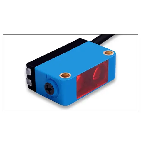
BGS-CX441 / BGS-CX442 Background Suppression Photoelectric Sensor
Wire-adjustable BGS sensor with 2 mm or 15 mm spot, 10-300 mm range, published black/white differential distance.

DDA-Y & DDB-Y Industrial Laser Distance Sensor (Phase-Shift)
Phase-shift laser distance sensors: 0.2-100 m range, millimeter accuracy, RS485 Modbus RTU, switching or analog output.
Related Products in Relay & Timer Modules
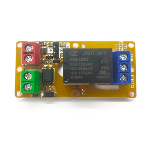
A1J0101 Economical Input Amplifier Module
Optocoupler-isolated input amplifier that turns a low-voltage signal into a 250V AC / 10A relay output.
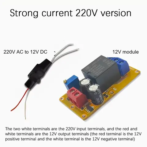
B2J0101 Economical Power-up Delay Module
Low-cost power-up delay relay module with a 2-30 second adjustable delay and no trigger input required.
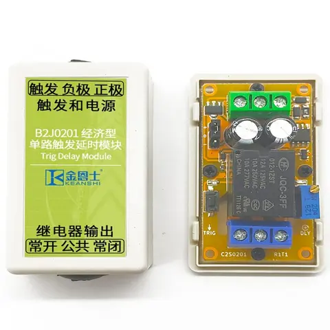
B2J0201 Economical Trigger Delay Module
Level-triggered delay relay module with jumper-selectable high/low trigger and a 2-30s adjustable delay.
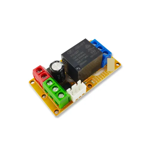
B2J0302 Enhanced Single MODBUS-485 I/O Module
Enhanced single-channel MODBUS-RTU/RS-485 I/O module: 1 digital input, 2 analog inputs, 1 relay or transistor output, AT command support and a 5V sensor supply — the successor to the discontinued B2J0301.