
D3J0302 Modbus
2-in/1-out Modbus-RTU/RS-485 I/O module with relay/transistor output for input acquisition and local control.
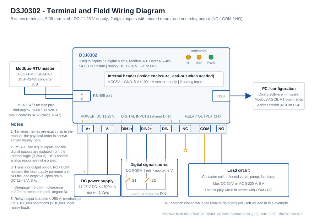 🔍 Click to enlarge · 1/3
Technical Specifications
| Order Code | D3J0302M111 (default: relay output, no pulse output, no wireless) |
|---|---|
| Product ID / Default Slave Address | 0x3302 |
| Inputs | 2-channel fully isolated digital input (plus 2 analog inputs, 1 x 5V/100mA power output) |
| Outputs | 1-channel digital output, relay or transistor type selectable (plus up to 2 high-speed pulse PWM/PTO outputs) |
| Communication Interface | RS-485 (Modbus-RTU, default 9600/8-Even-1); optional 2.4GHz wireless |
| Supply Voltage | DC 11-28V |
| Physical Interface | RS-485 half-duplex, differential twisted pair A/B; plus USB port; optional 2.4GHz wireless Modbus-OTA |
| Communication Protocol | Modbus-RTU (primary); plus Modbus-ASCII, AT commands; wireless Modbus-OTA |
| Default Baud Rate | 9600 bps |
| Default Data Format | 8 data bits, even parity, 1 stop bit |
| Default Slave Address | 0x02 |
| Optional Baud Rates | 300 / 600 / 1200 / 1800 / 2400 / 4800 / 7200 / 9600 / 14400 / 19200 / 28800 / 38400 / 56000 / 57600 / 76800 / 115200 bps |
| Optional Parity | None / Odd / Even (default Even) |
| Optional Stop Bits | 1 (default) / 1.5 / 2 |
| Slave Address Range | 1-247 (0x01-0xF7) |
| USB Mode Address | Fixed at 0x01 when USB is connected; RS-485 then switches to master mode |
| Input Threshold | Approx. 3V |
| Input Counting | Per-channel DINnCNT, increments on rising edge; rolls over at 65535, clearable by write |
| Input Filtering | Per-channel DINnFLT, adjustable (0=off), savable through power loss |
| Output Control | DOUTnDV register written by host; supports output polarity reversal and coil forcing |
| Output Delay Modes | 5 delay (jog) modes; output turns on when the trigger condition is met and turns off automatically after a configurable delay |
| Local Input-Output Linkage | Digital output can be triggered directly by its matching-numbered digital input (output n linked to input n) without host intervention |
| Emergency Brake | Designated limit/e-stop inputs force the output to a preset safe state (BRKFLG flag), highest priority, no host intervention required |
| Pulse Outputs | Up to 2 high-speed pulse channels for standard PWM speed control or PTO stepper/motor drive (segmented PGM program); fast PWM available on high-speed transistor channels (FPWM0PRD period / FPWM0DTY duty cycle) |
| Supply Ripple | < 1Vp-p |
| Supply Current | < 1500mA |
| Communication Port Stress | DC 0-5V |
| Input Port Stress | DC 0-30V |
| Relay Output Stress | DC 30V or AC 0-220V, 8A |
| Normal Transistor Output Stress | DC 12-48V, 8A |
| High-Speed Transistor Output Stress | DC 12-24V, 8A |
| Communication Isolation Voltage | < 250V |
| Input Isolation Voltage | < 250V |
| Output Isolation Voltage | Relay type < 250V; transistor type < 130V |
| Operating Temperature | -20 to 60C |
| Max Supply Voltage (absolute) | DC 28V |
| One-Time Fuse | DC 250V, 3000mA, slow-blow |
| Max Communication Port Stress (absolute) | DC 50V |
| Max Input Port Stress (absolute) | DC 50V |
| Max Relay Output Stress (absolute) | DC 30V or AC 0-220V, 8A |
| Max Normal Transistor Output Stress (absolute) | DC 55V, 10A |
| Max High-Speed Transistor Output Stress (absolute) | DC 40V, 10A |
| Max Communication/Input Isolation Voltage (absolute) | DC 1000V, 60 seconds (type test only) |
| Max Output Isolation Voltage (absolute) | Relay type DC 1000V, 60 seconds; transistor type DC 250V, 60 seconds (type test only) |
| Relay Mechanical Life | Over 100,000 operations (over 10,000 under heavy load, varies with load) |
| Storage Temperature | -40 to 85C |
| Transistor Output Protection | Open-drain output with built-in 10A flyback diode, can directly drive up to 10A inductive loads (solenoids, motors); may briefly false-trigger for about 100ms during power up/down, so the recommended sequence is module power on before the output side and power off after it |
| Configuration Protection | Writing to sensitive registers (name, serial port, wireless, etc.) requires unlocking by writing ASCII "UL" to the security lock register, which automatically re-locks after each write |
| ESD Immunity | 4kV to all terminals -> normal operation (Criterion A) |
| EFT Immunity | 2kV/5kHz/2min -> normal (A); 4kV/5kHz/2min -> no permanent damage (C) |
| Surge Immunity | 1kV, all terminals to ground -> no permanent damage (C) |
| Creepage Distance | > 6.5mm measured (requirement > 6mm, pollution degree 3) |
| Clearance | > 2.2mm measured (requirement > 2mm, pollution degree 3) |
| Input/Output Response Time | Typical 20ms |
| Serial Command Reply Time | Max 25ms |
| Module Dimensions (L x W x H) | 54 x 88 x 59mm (tolerance +/-5%) |
| Terminal Pitch | 5.08mm |
| Terminal Count | 8 screw terminals |
Overview
The D3J0302 is a 2-channel fully isolated digital input plus 1-channel digital output module built around a dedicated ASIC and communicating over RS-485 using the Modbus-RTU protocol. It both reads digital input status (switches, limit switches, proximity sensors) and drives a relay or transistor output from the host controller on a single board, aimed at machine builders, panel integrators, and edge-node designers who need input acquisition and output control in one small unit instead of separate input and output modules.
Communication defaults to 9600 bps, 8 data bits, even parity, 1 stop bit, slave address 0x02, with a supported address range of 1-247. The output can be ordered as relay type (DC 30V or AC 0-220V, 8A) or transistor type (DC 12-48V or DC 12-24V, 8A), and each digital output can be linked directly to its matching-numbered input for local control without the host controller. The module also includes a USB port, 2 auxiliary analog input channels, up to 2 high-speed pulse outputs for PWM/PTO, and a 5V/100mA sensor power output.
Features & Benefits
One Module Instead of Two - Reads Signals and Switches Loads
Most RS-485 remote I/O forces you to buy an input module and an output module, wire both, and give both an address. The D3J0302 puts 2 fully isolated digital inputs and 1 digital output on a single 54mm-wide board with 8 screw terminals, so a two-sensor, one-actuator machine needs one device, one address and one power feed. It is the smallest entry point into the D3J03 family, which scales to D3J0304 (4-in/2-out), D3J0308 (8-in/4-out) and D3J0312 (12-in/8-out) on the same protocol.
Keeps the Machine Safe When the Bus or the Host Dies
Output n can be linked directly to input n so the output follows its own input with no host traffic at all, and the emergency brake forces the output to a preset safe value the moment a designated limit or e-stop input triggers, at the highest priority and flagged in BRKFLG. Both run inside the module with a typical 20ms I/O response, so a cut RS-485 cable, a crashed PLC or a rebooting SCADA server does not leave the actuator stuck on.
Relay or Transistor Output Chosen by One Digit in the Order Code
The same product covers the AC and DC worlds. The default relay build (order code D3J0302M111) switches DC 30V or AC 0-220V at 8A and gives you a genuine NC/COM/NO dry contact isolated to under 250V. The transistor build is open-drain at DC 12-48V, 8A, with a 10A flyback diode already on board, so solenoids, electromagnets and motors up to 10A connect directly without you adding a suppression diode. No new part number to qualify - just the M[ddd] suffix.
Counting and Debouncing Happen on the Module, Not in Your PLC
Every digital input has its own rising-edge counter (DINnCNT, rolls over at 65535 and is clearable by a register write) and its own adjustable debounce filter (DINnFLT, 0 = off) that survives power loss. A vibrating limit switch or a chattering contact is cleaned up in the module, and pulse counting needs no high-speed counter card and no fast polling loop on the host.
Analog Inputs, PWM/PTO and Sensor Power Included, Not Extra
Beyond the 2 digital inputs and 1 output, every unit ships with 2 analog input channels for simple voltage measurement, a 5V/100mA output to power a sensor directly, and up to 2 high-speed pulse channels for PWM speed control or PTO stepper drive (fast PWM uses FPWM0PRD for period and FPWM0DTY for duty cycle). A greenhouse node can power its own moisture sensor, read the voltage and switch the sprinkler from one module, with nothing added.
Built for Dirty Panels: 2kV EFT, Double the Industrial Requirement
EFT immunity is tested at 2kV/5kHz for 2 minutes with normal operation (Criterion A), twice the 1kV that IEC61000-6-2-2016 requires of industrial equipment, plus 4kV ESD and 1kV surge with no permanent damage. On the PCB the high-voltage side is slotted for creepage: over 6.5mm measured against a 6mm requirement at pollution degree 3, and over 2.2mm clearance against 2mm. For sites with relentless EFT, the input-reinforced XS variant is a suffix on the order code, not a different product.
Commission It on a Laptop, Deploy It on RS-485
The included USB port is not an afterthought: it doubles as a USB-to-serial adapter, takes fixed address 0x01, and flips the RS-485 port into master mode so the module can drive other slaves on the bench - no RS-485 converter needed to configure it or update firmware. On the bus it is plain Modbus-RTU (FC 0x02 for discrete inputs, FC 0x03/0x06/0x10 for holding registers, plus 0x04, 0x16, 0x17 and 0x11 report device ID), and Modbus-ASCII and character-based AT commands are there for touchscreens, PLCs and quick scripts.
Settings That Cannot Be Knocked Out by a Stray Write
Sensitive registers - device name, serial port parameters, wireless - sit behind a security lock: you write ASCII "UL" to unlock, and it re-locks automatically after each single write, so a misaddressed command cannot silently change a commissioned module's baud rate. Supply-side protection covers reverse polarity, overcurrent, surge and automotive load dump, and the input filter settings are saved through power loss, so a site power cut does not undo your tuning.
Applications
Models & Ordering Information
D3J0302
How to Select
- Choose the D3J0302 (2-in/1-out) for single- or dual-point input acquisition with a single output on small devices and edge nodes; it is the smallest and lowest-cost model in the D3J03 input+output family, about 54mm long with 8 screw terminals.
- For more points, step up within the D3J03 input+output series: 4-in/2-out D3J0304, 8-in/4-out D3J0308, or 12-in/8-out D3J0312 for larger panels.
- Choose the transistor output option for inductive or high-current loads such as solenoids and motors; choose the relay output option (the default) for standard AC loads.
- Use the pulse-output order code digit to add fast PWM/PTO capability, for example order code M231 enables high-speed transistor output 0 with fast PWM.
- Add the optional 2.4GHz wireless Modbus-OTA link where RS-485 wiring is inconvenient.
- For sites with frequent strong EFT, order the input-reinforced variant with suffix "XS".
📘 Need the full method? NPN vs PNP Sensor Outputs Explained
When NOT to specify the D3J0302 — and what to use instead
You need to read more than 2 digital inputs or switch more than 1 output on a single board
Why not: D3J0302 is fixed at 2 fully isolated digital inputs and 1 digital output - the entry point of the D3J03 combined input/output family.
Use instead: Step up within the same family to D3J0304 (4-in/2-out), D3J0308 (8-in/4-out) or D3J0312 (12-in/8-out).
Your device only has inputs to report, or only one output to switch, not both
Why not: Every D3J0302 unit ships with 2 inputs AND 1 output together on its 8 screw terminals; a monitoring-only or switching-only job pays for and wires a channel type it never uses.
Use instead: Use the pure-input D3J0104 or the pure-output D3J0202 module instead.
You plan to rely on the output-follows-input linkage or the BRKFLG emergency brake as the machine's certified e-stop or guard-interlock circuit
Why not: D3J0302 carries no Type/SIL/PL safety rating and its output is not an OSSD; the input linkage and the brake (typical ~20ms I/O response) are ordinary ASIC firmware features, not a certified safety function. Both run locally on the module without the host, which is exactly why they get mistaken for a safety function, but they are not one.
Use instead: Use a dedicated DA31 Emergency-Stop Safety Relay Module or DQSRN Safety Relay Module for any real safety function.
Your single actuator draws more than 8A, or needs AC above 0-220V or DC above the relay's 30V rating
Why not: The relay output is rated DC 30V or AC 0-220V at 8A; the transistor option is DC 12-48V (normal) or DC 12-24V (high-speed) at 8A, with only a 10A absolute maximum even with the built-in 10A flyback diode.
Use instead: Drive the load through an external contactor or relay sized for it, switched from the D3J0302 output.
You need logic beyond a single input directly driving its matching output - for example two conditions that must both be true, or a timed sequence
Why not: D3J0302's local intelligence is limited to per-channel input-to-output linkage, 5 jog/delay modes, and the emergency brake; there is no user-programmable logic engine on board.
Use instead: Use the D4G0206 micro-PLC where real programmable logic is required.
Your system runs a fieldbus other than Modbus-RTU, such as Profibus or EtherNet/IP
Why not: D3J0302 communicates only over RS-485 Modbus-RTU (default 9600bps, 8 data bits, even parity, 1 stop bit, slave address 1-247), plus Modbus-ASCII, AT commands, and an optional 2.4GHz Modbus-OTA wireless link.
Use instead: Choose an I/O module or gateway that natively speaks your fieldbus.
Specifications we do not publish yet
We only publish a figure once we are confident it is true. The items below are still being validated through further testing and real-world customer feedback, so for now we would rather leave them open than guess. If one of them matters to your design, ask us for the latest validated status.
- Mean time between failures (MTBF) for the module - not published
- Ingress protection (IP) rating of the enclosure - not stated in the source manual
- Full EMC compliance (radiated/conducted emissions, RF immunity) beyond the documented ESD/EFT/surge test results - not published
- Resolution, accuracy and input voltage range of the 2 analog input channels - only described as voltage measurement, no numeric spec given
- PWM/PTO pulse output frequency range and step/pulse-count limits - no numeric value documented
- Wire gauge accepted by the 8 screw terminals - not stated
- Maximum number of RS-485 nodes per bus segment and maximum cable length - not stated
- Module weight (only L x W x H = 54 x 88 x 59mm is given) - not documented
Frequently Asked Questions
What is the D3J0302 used for?
Can I choose between relay and transistor output?
Can the D3J0302 control its output without a host controller?
Can the D3J0302 be configured or operated over USB instead of RS-485?
What extra I/O comes with the module besides the 2 inputs and 1 output?
What are the default communication settings?
Does the D3J0302 have any certifications?
Related Categories and Example Products
Explore other functions that may be needed in a machine or line. The products below are category examples, not pre-validated electrical or safety combinations. Confirm each interface and application separately: Proximity Sensors · Photoelectric Sensors · Laser Distance Sensors
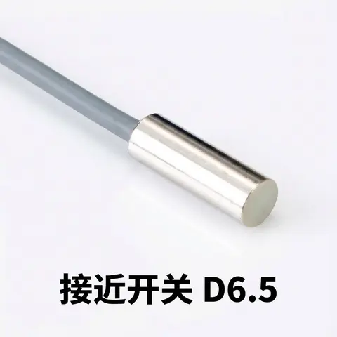
D6.5 Series Inductive Proximity Sensors (Ultra-Short 18mm / Y-Type / 35mm / 45mm)
6.5mm-diameter inductive proximity sensors for tight-clearance mounting where M8 sensors won't fit.
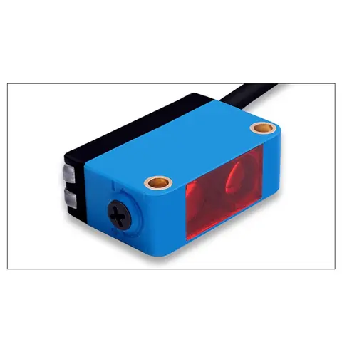
BGS-CX441 / BGS-CX442 Background Suppression Photoelectric Sensor
Wire-adjustable BGS sensor with 2 mm or 15 mm spot, 10-300 mm range, published black/white differential distance.
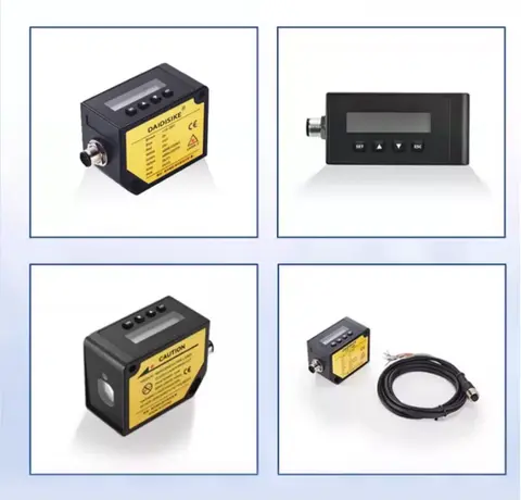
DDA-Y & DDB-Y Industrial Laser Distance Sensor (Phase-Shift)
Phase-shift laser distance sensors: 0.2-100 m range, millimeter accuracy, RS485 Modbus RTU, switching or analog output.
Related Products in Relay & Timer Modules
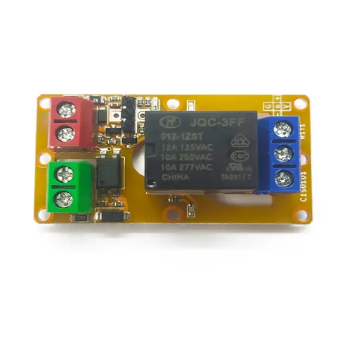
A1J0101 Economical Input Amplifier Module
Optocoupler-isolated input amplifier that turns a low-voltage signal into a 250V AC / 10A relay output.
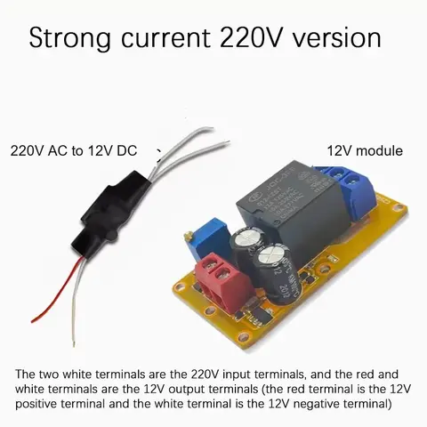
B2J0101 Economical Power-up Delay Module
Low-cost power-up delay relay module with a 2-30 second adjustable delay and no trigger input required.
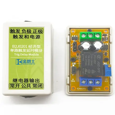
B2J0201 Economical Trigger Delay Module
Level-triggered delay relay module with jumper-selectable high/low trigger and a 2-30s adjustable delay.
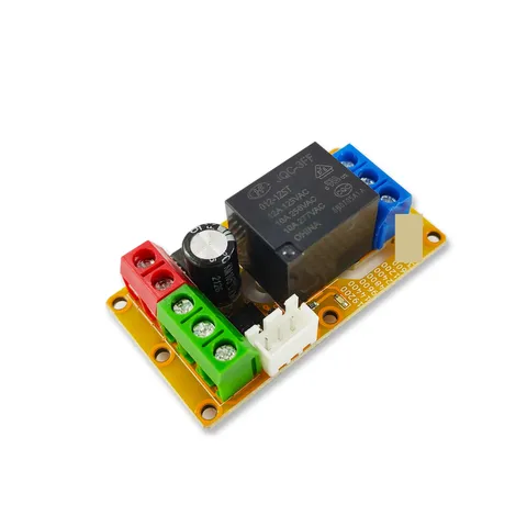
B2J0302 Enhanced Single MODBUS-485 I/O Module
Enhanced single-channel MODBUS-RTU/RS-485 I/O module: 1 digital input, 2 analog inputs, 1 relay or transistor output, AT command support and a 5V sensor supply — the successor to the discontinued B2J0301.