
Press Brake and Punch Press Light Curtain Guarding: What Actually Fails on the Factory Floor
A fitted light curtain does not, by itself, prove that a press is safeguarded. The stop path, stopping performance, detection capability, access geometry and operating modes all affect the result. A buyer needs evidence for those decisions as well as an order code.
This article is a purchasing and design-review checklist, not a published incident study or a report of verified customer assessments. The numerical examples below are hypothetical and explicitly limited to historical arithmetic; a qualified integrator must determine the current applicable installation requirements.
Keep the distinction between sensor and safety function clear: an indicator changing colour is not proof that hazardous motion stops in time. Where protection is absent, defeated or uncertain, do not rely on it for production; follow the site's safe isolation and escalation procedure.
The short answer: what a correctly guarded press looks like
Before selecting equipment, request evidence for the complete safeguarding arrangement. The following questions apply to the review; they are not a declaration that every press can be made compliant by fitting the same light curtain.
Document who is responsible for each item and which machine, tool setup and operating mode it covers. Physical tests belong to competent personnel following an approved safe procedure, not to an untrained buyer walking up to a running machine.
- The protective device and complete safety function meet the required performance and applicable machine rules; ordinary measuring or photoelectric sensors are not substituted for personnel safeguards.
- The exact output and controller arrangement commands the required safe response through the final switching elements.
- Positioning is based on the applicable method, actual detection capability and measured maximum stopping performance for the relevant machine conditions.
- Rated detection capability is recorded separately from beam pitch; protective height and arrangement cover all relevant approaches.
- Reach-over, reach-under, side/back access and a person remaining behind the detection field are addressed.
- Required diagnostics, reset/restart prevention and—where the machine rules require it—brake monitoring are documented and validated.
- Production, setup, fault recovery and maintenance have approved modes and procedures; no uncontrolled bypass is needed to perform the task.
Follow the Complete Stop Path, Not Just the Sensor Indicator
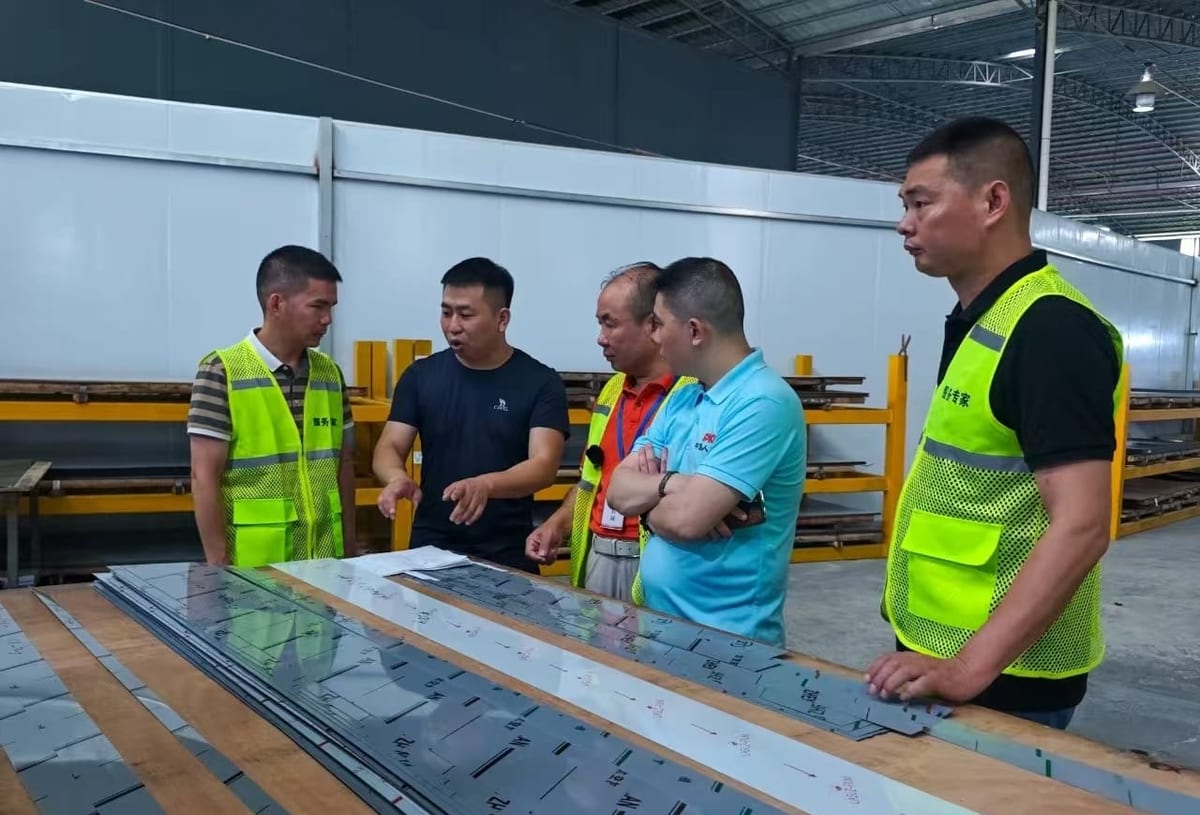
Read the arrangement from left to right: the protective device detects the relevant interruption, the safety logic evaluates the exact outputs, the final elements command the required response, and the machine reaches its defined safe state. A green or red indicator is useful status information; it is not evidence that the complete path works.
For a shortlist, compare the DQS curtain-and-controller arrangement with the other press and press-brake protection options. Then request the selected controller's functions, machine interface and required reset/restart and diagnostic arrangements. A catalogue set is not automatic compatibility approval.
Keep the response record traceable to the actual configuration. If the integrator measures a complete stopping time, do not add the same sensor, logic or actuator delay twice. The diagram is a review aid, not a terminal drawing, timing guarantee or separation-distance calculation.
Evidence to Request From the Supplier and Integrator
A supplier's useful contribution is a traceable model and configuration record, not an unsupported claim that a particular installation was audited or made safe.
Request the exact sensor/controller manuals, output drawing, detection capability, response limits, available safety data and certificate scope. Ask the machine integrator for the risk assessment, safety-requirements specification, stop-time measurements, positioning calculation and validation record.
Start an enquiry with the information already available: machine type, production and access tasks, opening dimensions, a layout and the intended controller interface. Add the reachable body part or required detection capability if the integrator has established it. If measured stopping-time evidence is not yet available, mark it as pending; it is not a barrier to an initial product shortlist or quotation.
Before the order and installation are accepted, close the open items with the qualified integrator. DAIDISIKE can identify candidate products, quote the agreed configuration and state which supporting documents are available; the integrator must determine the required safety functions, select the required detection capability from exact-model evidence, calculate the separation distance and validate the complete arrangement.
Review the DQT4 published manuals and technical data and the download library for available files. For DQS, DKE-L3 or DQV, request documents for the exact configuration. Match every document and drawing to the quoted version, and record any unavailable evidence as an open item rather than assuming another series' manual applies.
This article does not assert participation in a government programme, a measured frequency of factory defects or customer assessment results without traceable project records. Those claims from the earlier version have not been used as evidence for the current recommendations.
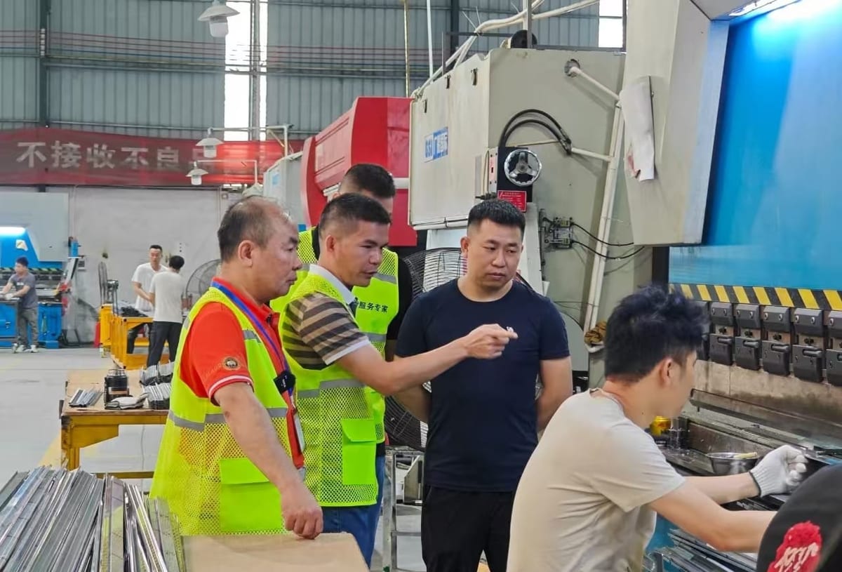
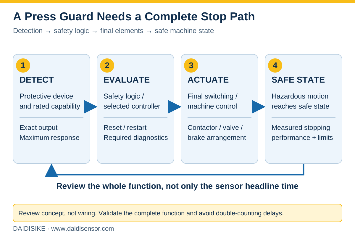
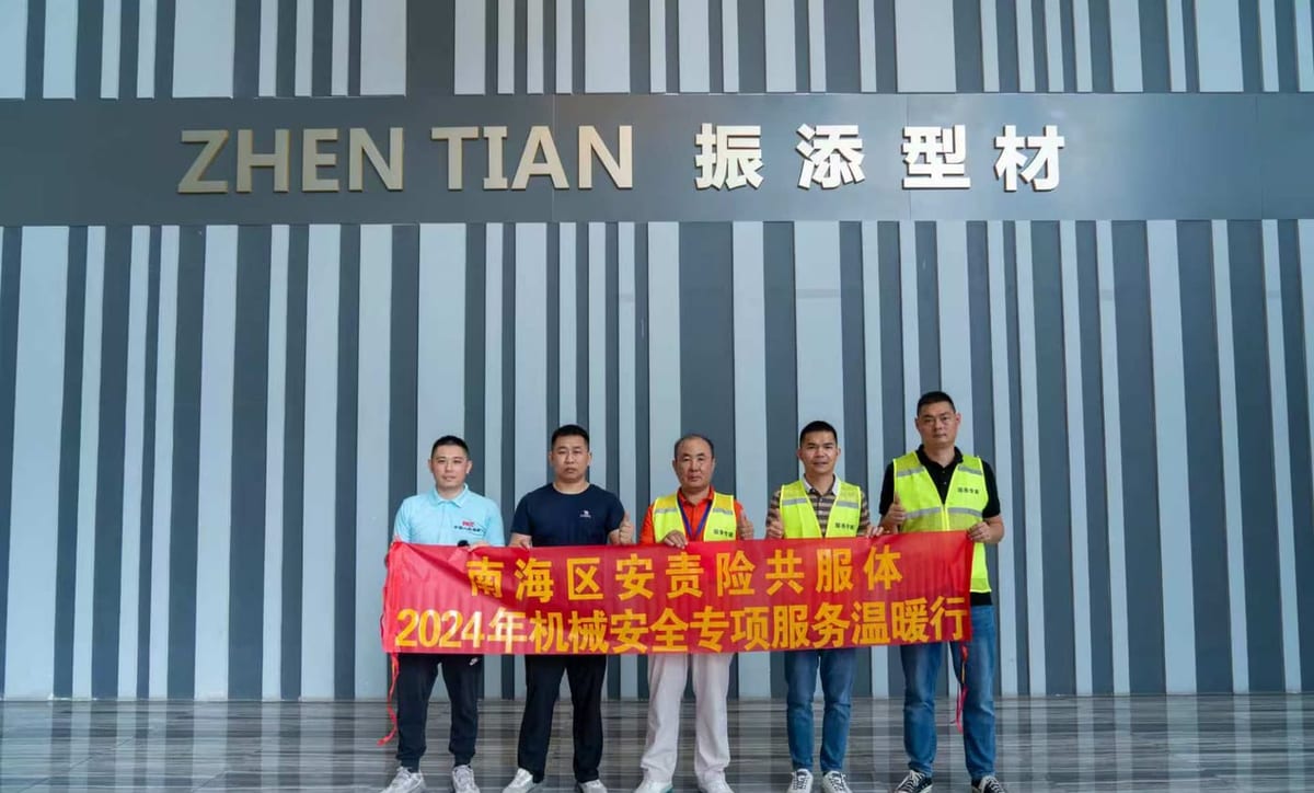
The retained workshop photographs are context material, not customer endorsements or proof of completed assessments. Any future named case study needs verified project facts and permission before publication.
| Purchase item | Initial enquiry and supplier response | Evidence to close before acceptance |
|---|---|---|
| Task and access | Buyer supplies available machine, task, opening and layout details; supplier identifies candidate product arrangements | Integrator confirms hazards, operating modes, all access routes and required safety functions |
| Order configuration | Quote exact sensor/controller versions, output, quantities and required interface | Confirm compatibility and an itemised scope for cables, connectors, brackets and accessories; do not assume they are included |
| Protection and positioning | List documented detection capability and response limits; mark missing stopping-time records as pending | Integrator closes the maximum stop-time record, applicable positioning calculation and whole-function validation |
| Documents and delivery | List available model-specific manuals, drawings and safety evidence with revisions; request quantity and destination | Agree document applicability, unresolved evidence, delivery scope and lead time in the quotation; a catalogue or CAD file is not installation approval |
Why Press Guarding Needs a Task-by-Task Review
Presses, press brakes and shears can expose people to closing tools, moving stock and other hazards during repetitive work. The relevant question is not which machine has the highest incident percentage, but how a person can reach the actual hazard in each task.
No traceable original source was established for the accident percentages previously printed here. They are not used as evidence in this review. Instead, identify the intended operation, foreseeable misuse and required risk-reduction measures for the particular installation.
For United States applications, OSHA 1910.212 addresses general machine guarding. OSHA 1910.217 has specific mechanical-power-press requirements and expressly excludes press brakes and certain other machines from that section. Do not transfer its detailed provisions automatically to every forming machine.
Setup, tool changes, clearing faults and maintenance can require different protective measures from normal production. Specify safe access, isolation, mode selection and responsibility for those tasks before the equipment is purchased.
Five Integration Failure Patterns to Check
These are qualitative review categories, not a frequency-ranked field survey. Their presence or absence must be established from the actual machine and its records.
Pattern 1 — A sensor indication without a validated stop path. Confirm how the protective output reaches the logic and final elements, and how the hazardous condition is brought to a safe state. A lamp, buzzer or normal PLC input alone does not demonstrate that safety function.
Pattern 2 — Defeat or an uncontrolled bypass. Review whether tooling, material flow or maintenance encourages an operator to bypass the device. Provide an approved safe method for the task and controlled access to configuration. Do not treat blanking or muting as a way to hide an unresolved access problem.
Pattern 3 — A mounting position without stopping-performance evidence. Mechanical convenience does not establish separation distance. Retain the relevant maximum stop-time measurements and approved calculation, and reassess changes to tooling, loading, brakes, valves or operating modes.
Pattern 4 — Detection capability confused with beam pitch. A 14 mm pitch is not necessarily a 14 mm detectable object. Use the exact documented test-object size, account for configuration changes and review every accessible route.
Pattern 5 — Required fault detection or restart measures absent. Establish how failures in the final elements are diagnosed and how unexpected restart is prevented. The necessary measures depend on the required performance and machine rules; a generic 'safety relay' label does not prove they are present.
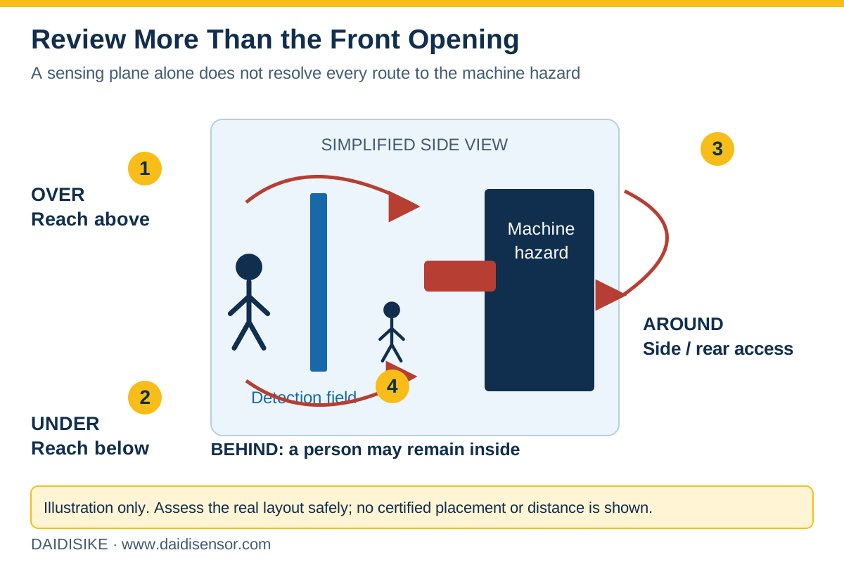
Review Over, Under, Around and Behind the Detection Field
A protective field across the front opening does not automatically cover every route to a hazard. Review reach-over, reach-under and access around the sides or rear; also consider whether a person can pass through the field and remain inside after the beams clear. Use the actual opening, tooling, stock and task layout rather than copying this simplified illustration.
A rear or side opening may need fixed guarding, an interlocked access arrangement or another assessed measure. The DQV double-sided protection device and guard-locking and door-monitoring products are candidates to investigate, not a universal answer. Their role, outputs, restart prevention and complete circuit need application-specific verification.
Record the rated detection capability separately from beam pitch using the light-curtain selection guide. Check all access routes from drawings and safely isolated equipment under a competent person's procedure; never attempt reach tests at a live machine hazard.
Press Brakes: Match the Safeguard to the Bending Task
Press-brake safeguarding depends on tooling, stock support, hand position, ram behaviour, operating modes and access from every side. Do not assume all arrangements suitable for a punch press transfer to bending.
A fixed vertical light curtain can be appropriate in an assessed arrangement, but some hand-feeding tasks may conflict with the required sensing plane or separation distance. That conflict must be resolved by an appropriate safeguarding design, not by uncontrolled blanking or a blanket rule that fixed curtains are always forbidden.
A ram-associated laser guard is another product arrangement to evaluate. DKE-L3 is described as a transmitter/receiver three-beam system; do not infer that it is an AOPDDR under IEC 61496-3 simply because it uses a laser. Request its actual optical principle, applicable device standard, safety evidence and controller-specific muting/field functions. Compare it with the alternatives in press and press-brake protection.
For box or complex bending, confirm whether the selected system supports the required field changes, under what conditions they are permitted, and how full protection is restored. A sales description cannot replace the exact configuration and validation instructions.
Rear and side access need their own protective measures. The DQV double-sided protection arrangement is a catalogue option to investigate alongside fixed guarding and interlocked access; its applicability and complete circuit must be verified.
Include the pedal/control arrangement, setup and recovery modes, tooling clearances and the risk from the moving workpiece in the specification. An optical device does not remove every hazard arising during bending.
What to specify for a punch press or shear
DQS is a catalogue option for a curtain-and-controller arrangement. Specify the exact sensor, controller, output version and machine interface together; buying a set does not eliminate integration or validation work.
Use the following table to request order-specific evidence. Published catalogue values are not a blanket confirmation of every option or an independent certification.
Check the configured maximum response of the whole arrangement, not just the sensor's headline figure. Do not assume EDM or reset features from the controller family name; obtain the actual function and circuit documentation.
The DQC product page includes specific output and detection limitations. The DQT4 product page distinguishes 7.5/15/30 mm pitch from 14/21/36 mm detection capability. Neither link approves a press application. The safety-relay comparison supports input/contact review; DQSRN supports manual and automatic reset per its selected-model instructions; EDM capability remains unconfirmed.
The light-curtain selection guide covers opening and detection choices, while the Type 2/Type 4 purchasing evidence checklist covers claim verification. The video library is explanatory material, not validation of the viewer's machine.
| Parameter | DQS series |
|---|---|
| Safety evidence | Request exact sensor/controller version, applicable Type/PL evidence and certificate or test scope |
| Beam pitch | 10 / 14 / 20 / 25 / 30 / 40 / 80 mm catalogue choices; obtain detection capability separately |
| Response | Catalogue sensor figure ≤10 ms; verify controller and complete configured response |
| Sensing range | 0.3–3 m up to 0.3–40 m, selected by order code |
| Output and control functions | Confirm exact relay/transistor arrangement; do not assume reset or EDM |
| Controller contact rating | AC 250 V / 5 A or DC 30 V / 5 A |
| Supply | Sensor DC 12/24 V; controller AC 110–220 V ±15% |
| Enclosure | Published IP65; verify actual conditions, connectors and cleaning process |
| Housing section | Approx. 35 × 51 mm |
A 12-Point Evidence Checklist for Qualified Verification
This checklist helps the buyer request commissioning evidence. It is not permission to approach, interrupt or modify a running machine. Testing requires competent personnel, an approved safe procedure, appropriate equipment and control of hazardous energy.
Inspection and measurement intervals follow the machine instructions, risk assessment and applicable requirements. Revalidation after relevant changes is separate from routine checks; a universal annual schedule is not sufficient for every press.
Additional hazards may require different devices: safety edges detect contact at a moving edge, and safety mats can support presence detection where correctly designed. Their selection and controller compatibility need the same evidence discipline.
- 1. Safe-response test record. Qualified personnel must validate the specified stop under a controlled procedure, using the manufacturer-prescribed test object—not a hand or body.
- 2. Complete circuit. Identify input, logic, final switching elements and the safe state; confirm status indication is not the only response.
- 3. Defeat review. Document and resolve unapproved bypasses and configuration changes under controlled access.
- 4. Access assessment. Check drawings and safely isolated equipment for reach-over, under, around, behind and tool-change access; never attempt reach tests at a live hazard.
- 5. Stopping performance. Obtain dated maximum measurements, conditions and the applicable separation-distance calculation.
- 6. Actual positioning. Compare the measured installation with the approved layout and calculation.
- 7. Detection capability. Verify the rated test-object size and any blanking/configuration effect separately from beam pitch.
- 8. Coverage. Confirm the full reachable opening and the risk of a person remaining behind the field.
- 9. Diagnostics. Retain validation of required final-element monitoring using an approved test procedure; do not improvise a welded-contact simulation.
- 10. Machine-specific functions. Verify required clutch/brake control, brake monitoring and other provisions for the actual machine and mode.
- 11. Reset and restart. Verify deliberate procedures, location, visibility and prevention of hazardous unexpected restart.
- 12. Non-production tasks. Record the approved isolation, setup, maintenance and recovery arrangements so the task does not depend on an uncontrolled bypass.
Safety Distance: Limited Historical Arithmetic, Not an Installation Design
The underlying question is whether the complete application reaches a safe state before a person can reach the hazard. Current installation decisions need the applicable standard edition, machine requirements, actual approach geometry and measured stopping performance.
The arithmetic below illustrates only the legacy ISO 13855:2010 perpendicular-approach method for detection capability d from 14 to 40 mm. ISO 13855:2010 has been replaced by ISO 13855:2024. These examples are not approved separation distances for a new or existing machine.
Historical example: S = K × T + C, with C = 8 × (d − 14). T is in seconds and d is the rated detectable-object size, not beam pitch. For this limited method, start with K = 2000 mm/s and a 100 mm minimum. If the first result exceeds 500 mm, the 1600 mm/s recalculation has a 500 mm floor.
T must represent the relevant complete response to the safe state. A delay budget can include the sensor, safety logic and final-element/machine stop, but a measured total must not have the same delay counted twice. Allowances for deterioration and uncertainty must follow the applicable method rather than an arbitrary fixed margin.
Hypothetical example 1. Assume 10 ms sensor, 15 ms logic and 165 ms machine-stop contributions: T = 0.190 s. For d = 30 mm, C = 128 mm. The first result is 508 mm; the historical recalculation is 432 mm, so its 500 mm floor governs the arithmetic.
Hypothetical example 2. Assume d = 14 mm and T = 0.115 s. The same limited arithmetic gives 230 mm. This is a separate assumed input set, not evidence of a measured machine improvement or proof that a particular series detects fingers.
The examples show sensitivity to input assumptions. They omit reach-over, reach-under, step-through, whole-body/multi-beam arrangements, other approaches, machine-specific requirements and additional checks in the applicable current edition. Do not shorten an installed distance using this table.
North American requirements must be selected for the actual machine and operating mode. OSHA mechanical-press provisions and their PSDI provisions are not interchangeable, and neither is a universal press-brake formula. Retain the integrator's applicable rule, calculation and validation record.
| Rated detection capability d | C = 8 × (d − 14) | Initial 2000 × T + C | Historical result with applicable floor |
|---|---|---|---|
| 14 mm | 0 mm | 380 mm | 380 mm |
| 20 mm | 48 mm | 428 mm | 428 mm |
| 30 mm | 128 mm | 508 mm | 500 mm |
| 40 mm | 208 mm | 588 mm | 512 mm |
| >40 mm / other geometry | Outside this example | Not calculated | Separate applicable method required |
Scope, limits and honest caveats
Safety devices reduce risk. They do not eliminate it, and no supplier — including us — can promise that fitting a light curtain makes a machine safe. What determines the outcome is the risk assessment, the integration into the stop circuit, the calculated mounting distance, and the maintenance regime behind all three.
Nothing in this article replaces a risk assessment under ISO 12100 for your specific machine, or the determination of the required Performance Level under ISO 13849-1 (or SIL under IEC 62061) that follows from it. The formulas here are given so that you can ask your integrator informed questions, not so that you can skip the calculation.
Use the laws and machine-specific standards applicable to the location, machine type, manufacture/modification date and operating mode. ISO 16092-1:2017 is a starting scope reference for relevant presses, with further parts for specific press types; it is not a universal rule for every press brake or shear. Check current editions and national adoption before applying a provision.
Ordinary measuring curtains, DD/DDOF area sensors and general-purpose obstacle LiDAR must not be counted as personnel safeguards. For a protective device, request suitable exact-model evidence and validate its role in the complete function. The IEC 61496-3:2025 scope concerns diffuse-reflection protective devices; a laser transmitter/receiver pair does not acquire that classification merely by being optical.
Frequently Asked Questions
Does a safety light curtain on a press have to be interlocked with the machine control system?
How do I calculate the safety distance for a light curtain on a punch press?
Why can't I just fit a normal vertical safety light curtain to a press brake?
What resolution should a light curtain have for press guarding — 14 mm, 30 mm or 40 mm?
What is EDM and do I need it on a press?
How often should stopping time be re-measured?
What is the difference between blanking and muting on a safety light curtain?
Can I use a measuring light curtain or LiDAR to protect an operator on a press?
Do you supply and support press guarding for export customers?
Products Referenced in This Article
- DQS Press Photoelectric Safety Guard — Type 4 press light curtain plus dedicated controller: dual relay outputs wire straight into your press circuit.
- DKE-L3 Press Brake Laser Protection — Ram-mounted laser guarding that tracks the punch tip on press brakes and shears without blocking hand-fed work.
- DQV Double-sided Photoelectric Safety Protection Device — Guards two hazardous machine sides at once with independent light-curtain sets and dual output channels.
- DQT4 Type-4 Safety Light Curtain — Type-4-design safety light curtain in three beam-pitch grades — 7.5, 15 and 30 mm — reaching a 14 mm detection accuracy at the finest pitch, with protective heights from 90 mm to 5970 mm.