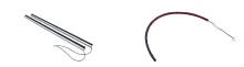
JB Series Safety Edge (Economy Line)

37 rubber cross-sections, 5-90 mm high — economical, form-fit pressure-sensitive safety edges for anti-pinch protection.

Technical Specifications

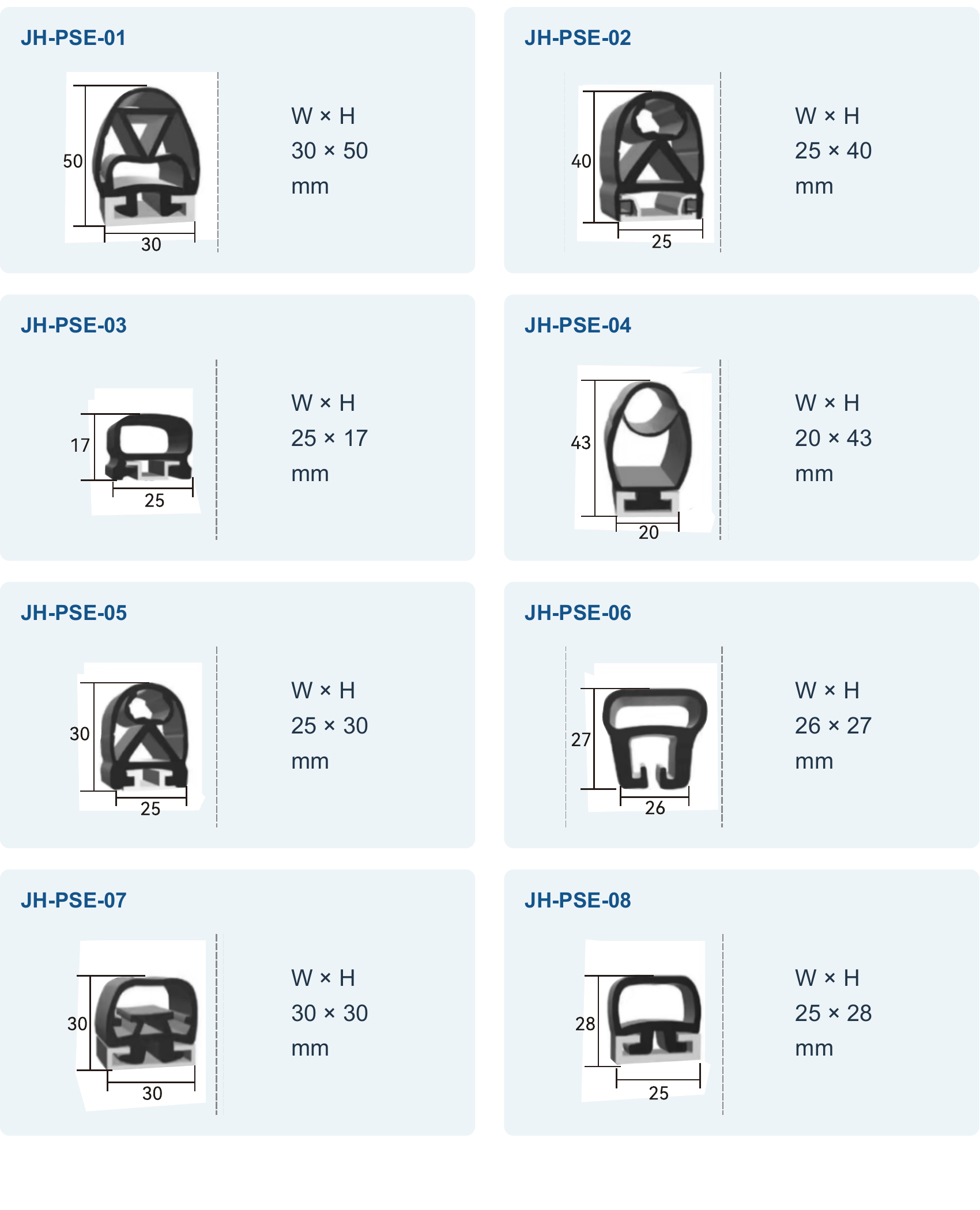
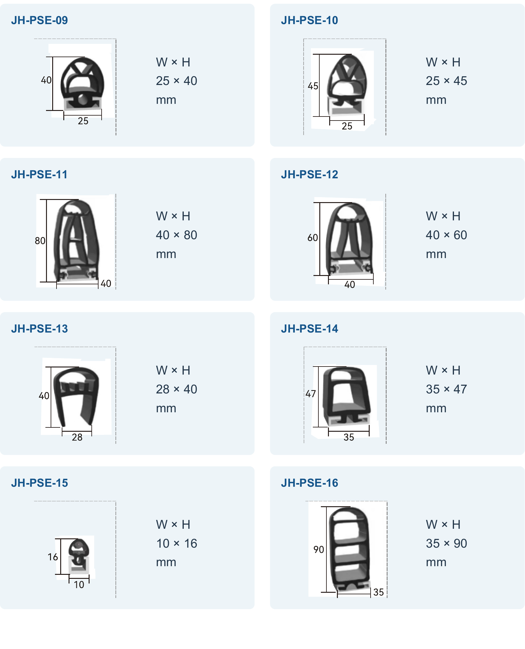
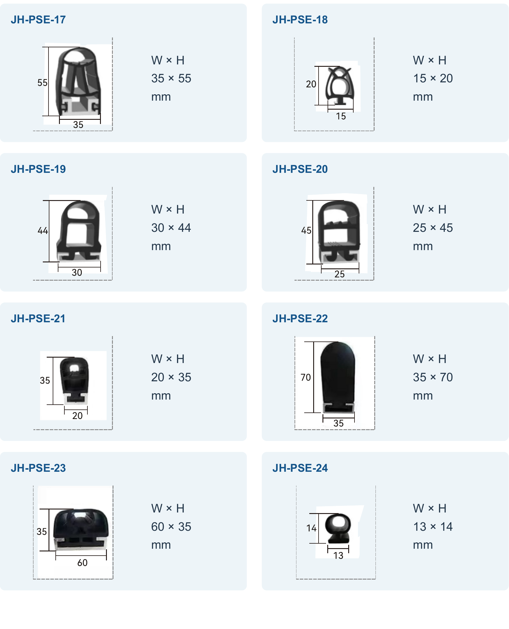
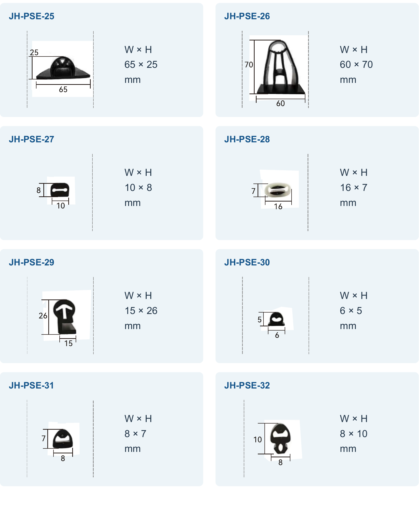
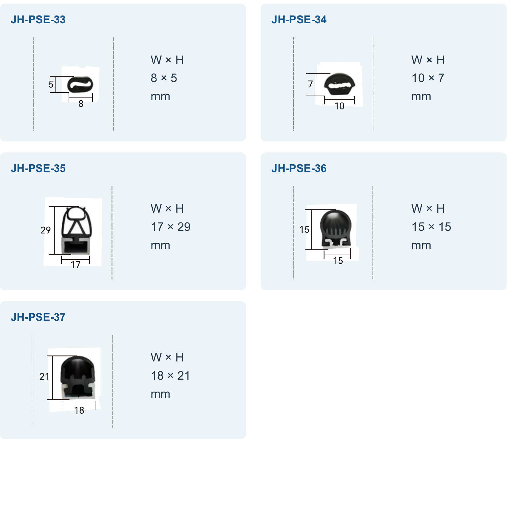
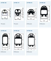
Cross-section profiles37 types, 5-90 mm high x 6-65 mm wide
Actuating force (catalog-listed models)≤ 30 N
Actuating travel (catalog-listed models)2-8 mm
Insensitive (dead) zone20-30 mm per side
Minimum bending radius≥ 55 mm to ≥ 350 mm, varies by profile (published for most, not all, profiles)
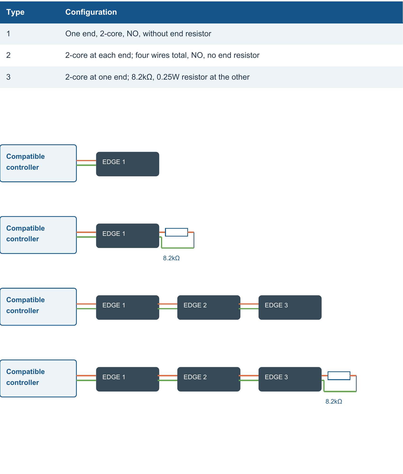
Max. series (daisy-chain) connection5 safety edges per controller input
Signal modeNormally open (N.O.); normally closed (N.C.) via interposing relay
Wiring configuration2-wire with 8.2 kΩ terminating resistor (R), or 2/4-wire without resistor (K)
Terminating resistor8.2 kΩ / 0.25 W
Rated voltage≤ 24 V
Rated current< 1 A
Standard cable length50 cm (customizable)
Cable diameter3.5 mm
Conductor cross-section0.25 mm² (copper)
MaterialBlack EPDM rubber
Operating temperature-20 °C to +80 °C
Ingress protectionIP65
Overall length20-300 cm, made to order; standard (R) or special-shape (S)

Overview

JB is an economy-line pressure-sensitive safety edge — a flexible rubber profile that trips a switching signal when compressed by contact. It protects the closing edge of doors, gates, and moving machine components from pinching or crushing a person or object, and is intended for general anti-pinch applications where a control unit or PLC already handles the safety logic.

The series offers 37 rubber cross-section profiles from 5 mm to 90 mm high and 6 mm to 65 mm wide, so it covers most door and machine edge geometries. Catalog-listed profiles switch at an actuating force of 30 N or less with a 2-8 mm actuating travel, and up to 5 edges can be daisy-chained to a single controller input, wired directly to a PLC e-stop input or, for normally-closed logic, through an interposing relay.

Features & Benefits

37 Cross-Section Profiles, 5-90 mm High

Covers virtually any door or machine edge geometry without redesigning the mechanical structure. Useful as a form-fit replacement for an existing worn safety edge.

Economy Line for General Anti-Pinch Protection

Pay for the protection you need in non-certification-mandatory scenarios, without the added cost of functional-safety performance data.

Low, Uniform Actuating Force

Catalog-listed profiles (32 of the 37) trigger at an actuating force of 30 N or less with an actuating travel of 2-8 mm, giving a consistent, gentle trip response.

Daisy-Chain Up to 5 Edges per Controller Input

Protect the full perimeter of a door frame or platform with a single circuit, reducing wiring and PLC I/O point cost.

2-Wire Monitored Version with 8.2 kΩ Terminating Resistor

An integrated 8.2 kΩ / 0.25 W terminating resistor lets the control unit continuously supervise the circuit for wire breakage and short circuits.

Direct-to-PLC Wiring Diagrams Provided

Wiring diagrams cover direct connection to a PLC e-stop input (normally open), or normally-closed operation via an interposing relay, so the edge integrates without a proprietary controller.

Custom Length, 20 cm to 300 cm

Order to fit your door width or edge length without on-site cutting or splicing, in standard (R) or special-shape (S) versions.

IP65-Rated EPDM Rubber, -20 °C to +80 °C

Suited to indoor and outdoor installation across a wide range of industrial conditions.

Conformable Mounting for Curved Edges

Profiles can be mounted along curved or irregular edges, and a minimum bending radius (from ≥55 mm) is published for most, though not all, of the 37 profiles.

Near Full-Length Sensing Coverage

Insensitive end zones of only 20-30 mm per side keep the effective sensing length close to the full length of the edge.

Applications

Closing Edge Protection for Sliding and Sectional DoorsMount the pressure-sensitive edge along the moving closing edge so contact with the edge immediately triggers the protective stop signal.
Crushing Point Protection on Moving Tables and Lifting PlatformsThe low actuating force (≤30 N) suits applications where the machine must stop on light human contact.
Curved Gates and Irregular Machine ContoursConformable mounting plus published minimum bending radius data for most profiles support installation along curved or irregular edges.
Full-Perimeter Guarding of a Door Frame via Daisy-Chained EdgesDaisy-chain up to 5 edges around the sides of a door frame or the perimeter of a platform, wired to a single controller input.
Retrofit / Replacement of an Existing Worn Safety EdgeWith 37 cross-section profiles covering a wide size range, match the groove or slot dimensions of an existing worn edge to find a form-fit replacement.
Indoor/Outdoor Industrial Doors and GatesIP65 protection and an EPDM sheath rated -20 °C to +80 °C suit both indoor and outdoor industrial installation.

Models & Ordering Information

Cross-Section Profiles (JB-1 to JB-37)

JB-1JB-2JB-3JB-4JB-5JB-6JB-7JB-8JB-9JB-10JB-11JB-12JB-13JB-14JB-15JB-16JB-17JB-18JB-19JB-20JB-21JB-22JB-23JB-24JB-25JB-26JB-27JB-28JB-29JB-30JB-31JB-32JB-33JB-34JB-35JB-36JB-37
The source catalog uses two numbering formats for this series — single-digit (JB-1...JB-37, used here) and zero-padded (JB-01...JB-37) — the formal SKU format has not been confirmed. Actuating-force/actuating-travel data is published for 32 of the 37 profiles (not available for JB-02, JB-04, JB-13, JB-18, JB-26). Minimum bending radius data is not published for JB-06, JB-16, JB-24, JB-28, JB-29, JB-30, JB-31, JB-32, JB-33, JB-34.

How to Select

  1. Select the cross-section profile (JB-1 to JB-37) by measuring the groove or edge dimensions to be protected — heights range from 5 mm to 90 mm and widths from 6 mm to 65 mm.
  2. Check the actuating force and actuating travel against the catalog parameter table, which covers 32 of the 37 profiles (actuating force ≤ 30 N, actuating travel 2-8 mm); confirm the remaining 5 profiles (JB-02, JB-04, JB-13, JB-18, JB-26) directly with the manufacturer.
  3. For curved or arc-shaped installation, prefer profiles with published minimum bending radius data (from ≥ 55 mm, varies by profile); profiles without published bending radius data should be confirmed with the manufacturer before curved installation.
  4. Choose the wiring configuration based on monitoring needs: select the 2-wire version with 8.2 kΩ terminating resistor (R) for wire-break/short-circuit supervision, or the 2/4-wire version without a resistor (K) if monitoring is not required.
  5. Match the signal logic to your control system: connect directly to a normally-open (N.O.) PLC e-stop input, or use an interposing relay for normally-closed (N.C.) logic.
  6. Specify the overall length to fit your door width or edge length, from 20 cm to 300 cm, in standard (R) or special-shape (S) form.
  7. Confirm the control circuit matches the signal loop rating: ≤ 24 V, < 1 A, with a standard 50 cm cable (customizable length).

When NOT to specify the JB — and what to use instead

A formal machine risk assessment requires documented PFH/Category/PL/SIL performance data for the safety edge itself

Why not: The JB series' own FAQ states it 'does not include published functional-safety performance data, over-travel specification, or response-time figures' in the current catalog.

Use instead: JB-PSE series, which carries published PFH, Category 3, MTTFd, and B10d data

Needing to detect presence at a distance rather than by direct contact

Why not: JB is a pressure-sensitive contact edge triggered by direct compression (2-8 mm actuating travel on catalog-listed profiles), not a non-contact presence sensor.

Use instead: A light curtain (DQC/DQA/DQT/DQT4) or ST27 laser scanner

Guarding a floor area instead of a single moving edge

Why not: JB is a linear edge profile (20-300 cm made to order); it is not a floor-coverage device.

Use instead: JT14 safety mat

The specific profile needed is one of the five without published actuating-force/travel data (JB-02, JB-04, JB-13, JB-18, JB-26)

Why not: The catalog parameter table covers only 32 of the 37 profiles for actuating force and travel; these five are not published.

Use instead: Confirm these five profiles directly with the factory, or select from the other 32 documented profiles

Curved or arc-shaped installation is needed on a profile without a published minimum bending radius (JB-06, JB-16, JB-24, and JB-28 through JB-34)

Why not: Minimum bending radius data is not published for these specific profiles in the current catalog.

Use instead: Confirm with the factory before curved installation, or select a profile with published bending-radius data

Specifications we do not publish yet

We only publish a figure once we are confident it is true. The items below are still being validated through further testing and real-world customer feedback, so for now we would rather leave them open than guess. If one of them matters to your design, ask us for the latest validated status.

  • Response time (not specified anywhere in the available catalog data for the JB series)
  • Actuating force/travel for JB-02, JB-04, JB-13, JB-18, and JB-26 (5 of the 37 profiles)
  • Minimum bending radius for JB-06, JB-16, JB-24, and JB-28 through JB-34
  • Formal SKU numbering format — the catalog shows both single-digit (JB-1) and zero-padded (JB-01) styles across source pages
  • PFH, MTTFd, B10d, Category, PL, and SIL figures (none published for this economy line)
  • Certificate numbers and issuing body for any compliance claim

Frequently Asked Questions

What is the actuating force of the JB safety edge?
For the catalog-listed models (32 of the 37 profiles), the actuating force is ≤ 30 N with an actuating travel of 2-8 mm. Data for the remaining 5 profiles is not published and should be confirmed with the manufacturer.
How many safety edges can be connected to one controller?
Up to 5 safety edges can be daisy-chained (series connected) to a single controller input, which is useful for protecting the full perimeter of a door frame or platform with one circuit.
Does the JB safety edge support wire-break/short-circuit monitoring?
Yes, a 2-wire configuration with an integrated 8.2 kΩ / 0.25 W terminating resistor is available so the control unit can continuously supervise the circuit for wire breakage and short circuits.
Can the JB safety edge connect directly to a PLC?
Yes, wiring diagrams are provided for direct connection to a PLC e-stop input (normally open), or for normally-closed operation via an interposing relay.
What lengths are available?
Any length from 20 cm to 300 cm is available made to order, in standard (R) or special-shape (S) versions.
What is the IP rating and operating temperature range?
The JB series is IP65-rated with an EPDM rubber housing, suitable for indoor and outdoor use across -20 °C to +80 °C.
Can the JB safety edge be installed on a curved door or arc-shaped gate?
The profiles are conformable and can be mounted along curved or irregular edges. Minimum bending radius data is available for most (but not all) of the 37 profiles; for profiles without published bending radius data, confirm with the manufacturer before curved installation.
Is the JB series functional-safety certified (e.g. SIL, Category, PL)?
Certification documents are available on request.
What is the response time of the JB safety edge?
Response time is not specified in the available catalog data for the JB series. This should be confirmed directly with the manufacturer if required for your application.
How does the JB economy line differ from a higher-end safety edge?
The JB line offers a much wider range of cross-section profiles (37 types) and a higher rated temperature ceiling in the source catalog, but does not include published functional-safety performance data, over-travel specification, or response-time figures that higher-tier lines may provide.

Works Well Together

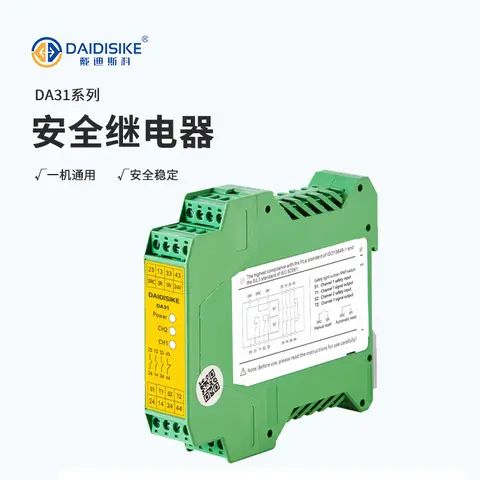
On the same machine or line, JB is typically ordered together with: Safety Relays · Safety Mats · Safety Door Locks & Switches
Related Products in Safety Edges

Browse all Safety Edges

Get a QuoteWhatsApp