JH-PSE Pressure-Sensitive Safety Edges
Seven main profiles and 37 extension profiles for contact detection on moving edges, powered doors and AGV bumpers.
 🔍 Click to enlarge · 1/3
Technical Specifications
| Detection | Pressure-sensitive contact detection |
|---|---|
| Main profiles | 108 / 110 / 215 / 230 / 245 / 345 / 360 |
| Extension profiles | 01-37 |
| Main-range length | 30-300 cm; custom lengths |
| Extension length | 20-300 cm; custom options |
| Main-range response | 13 ms; not total machine stopping time |
| Main-range life | >3,000,000 operations |
| Main-range material | 108/110: TPE; other main profiles: EPDM |
| Main-range temperature | -20 to +55 °C |
| Main-range ingress protection | IP65 |
| Main actuation angle | <90° |
| Extension temperature | -20 to +80 °C |
| Extension contact limits | ≤24 V; <1 A |
Overview
JH-PSE detects contact along a moving or closing boundary. Compression changes the sensing contact; a compatible controller and the machine's stop function then respond. The edge is a contact detector, not a non-contact protective field.
Choose from seven main profiles or 37 extension profiles. Main profiles use TPE or EPDM jackets and matched mounting bases. Extension profiles use black EPDM for compact, curved and shaped installations. Temperature, actuation data and cable arrangement depend on the selected group.
Seven Main Profiles: Dimensions and Actuation
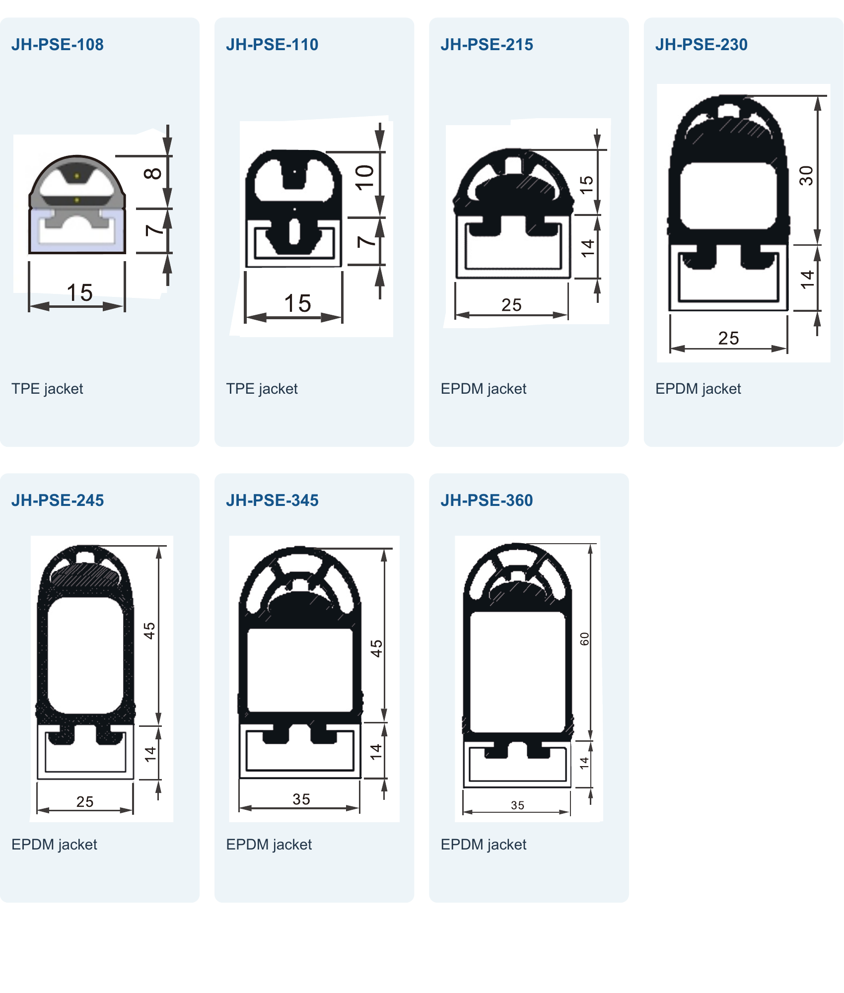
Rubber height and base height are separate dimensions. Dimensions and travel below are in mm; force is in N.
| Profile | Base W | Rubber H | Base H | Actuation travel | Force | Listed overtravel |
|---|---|---|---|---|---|---|
| JH-PSE-108 | 15 | 8 | 7 | <2 | ≤25 | 0 |
| JH-PSE-110 | 15 | 10 | 7 | <2 | ≤25 | 0 |
| JH-PSE-215 | 25 | 15 | 14 | <3 | ≤25 | 0 |
| JH-PSE-230 | 25 | 30 | 14 | <3 | ≤25 | <19 |
| JH-PSE-245 | 25 | 45 | 14 | <3 | ≤25 | <30 |
| JH-PSE-345 | 35 | 45 | 14 | <5 | ≤100 | <30 |
| JH-PSE-360 | 35 | 60 | 14 | <5 | ≤100 | <45 |
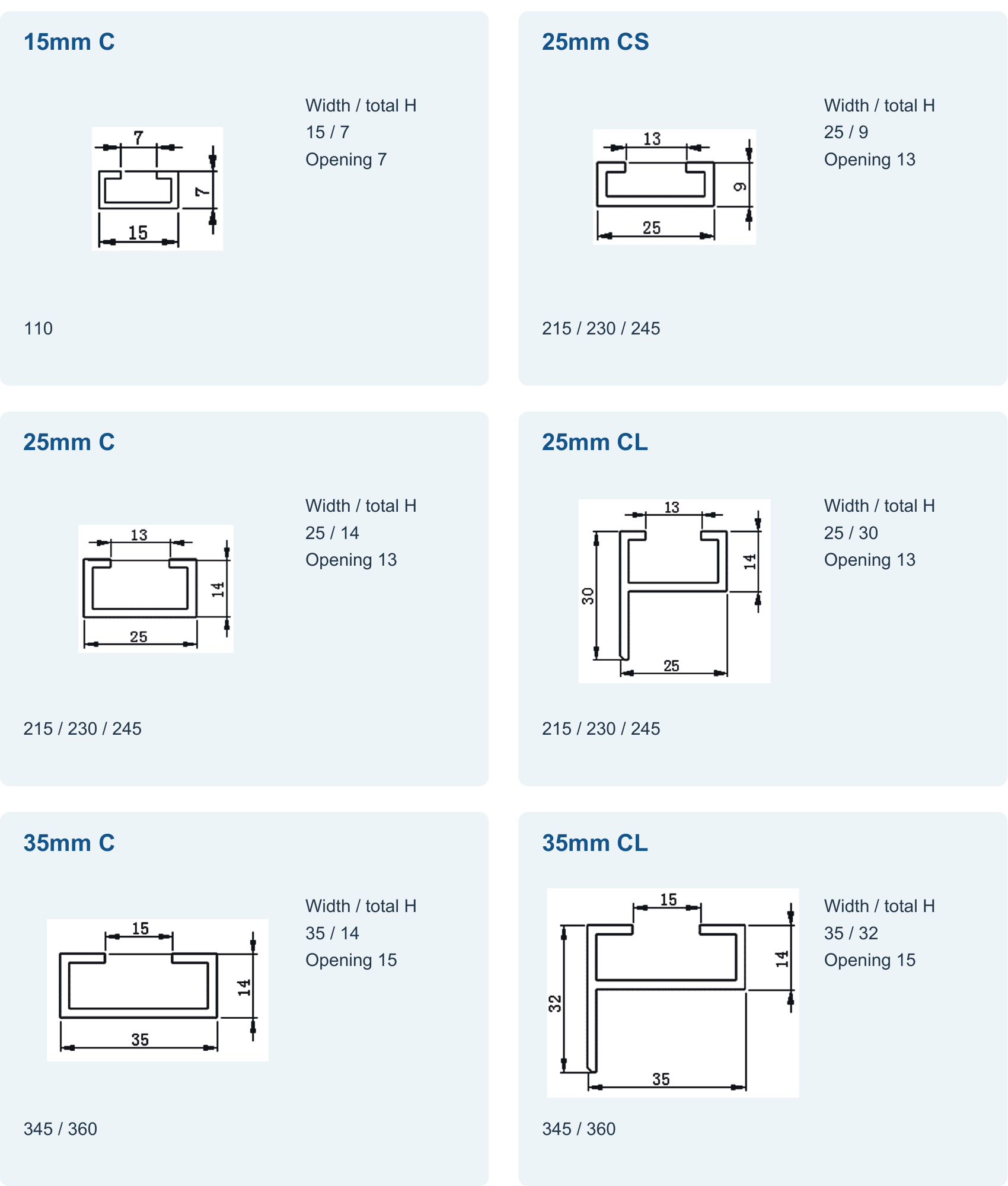
Profile-Matched Mounting Bases
R and K Electrical Configurations
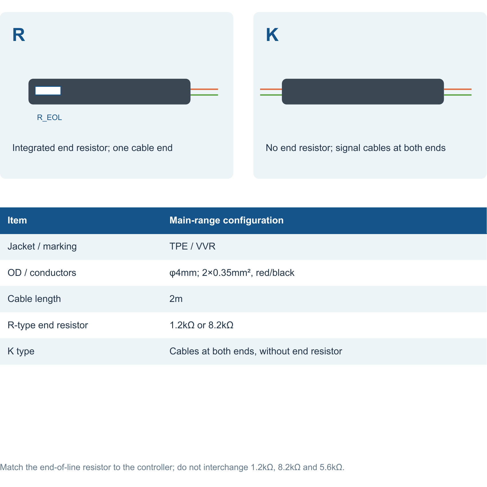
R uses a two-core connection with an end resistor. K uses a two- or four-core arrangement without an end resistor; the illustrated K layout has cables at both ends. The main-range cable is 2 m long, TPE/VVR, Ø4 mm, with 2 × 0.35 mm² red/black conductors.
37 Extension Profiles
JH-PSE-01 to -37 use black EPDM, lengths of 20-300 cm and a temperature range of -20 to +80 °C. Each end has a listed inactive zone of 20-30 mm.
The standard extension cable is 50 cm long, Ø3.5 mm, with 0.25 mm² copper conductors; custom options are available. The normally open sensing contact is separate from the controller's output logic.
Powered Doors and AGV Bumpers
Fit the edge to the hazardous contact boundary. Check active coverage, inactive ends, corners and travel remaining after actuation.
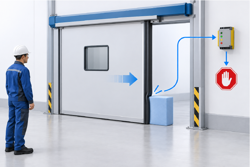
- 108: small AGVs. 110: small AGVs, garage doors and industrial equipment.
- 215/230/245: AGVs, powered doors and industrial moving edges.
- 345/360: larger bumpers, heavy doors and machine perimeters; stopping performance still determines suitability.
Allow for Motion After Contact
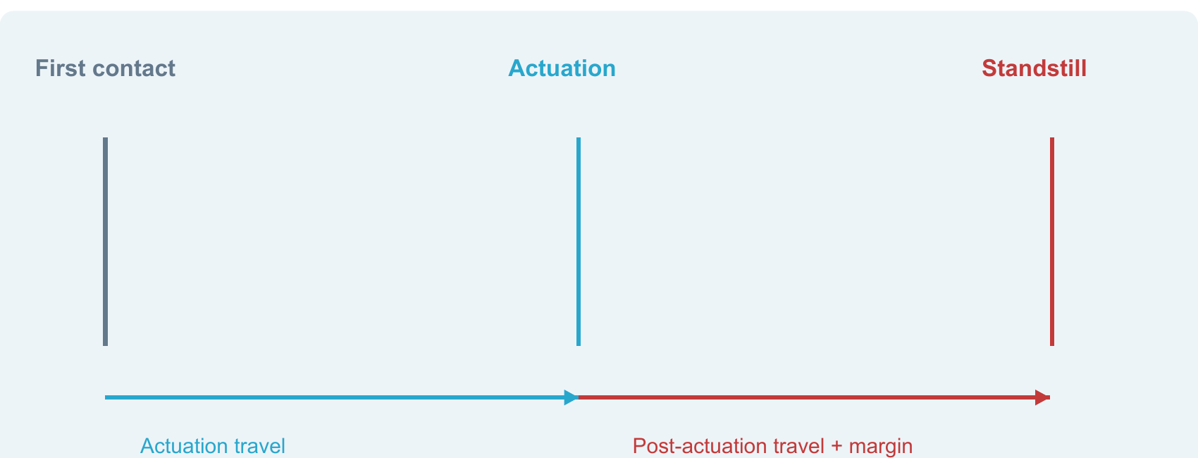
Match the safety controller, final switching elements and machine stop function. Reset must not initiate hazardous motion; provide a separate deliberate Start command.
Models & Ordering Information
Main profiles
Extension profiles
How to Select
- Select contact direction, section and mounting base.
- Compare profile-specific force, actuation travel and actual stopping allowance.
- Specify length, coverage, cable exit and termination.
- Match the controller and validate the complete machine stop function.
When NOT to specify the JH-PSE — and what to use instead
Non-contact protection is needed
Why not: The edge detects contact and compression, not approach at a distance.
Use instead: Select a suitable protective light curtain or scanner.
Motion exceeds permitted compression
Why not: Detection does not create mechanical stopping space.
Use instead: Revise and validate the guarding and stopping design.
Frequently Asked Questions
Are main and extension specifications identical?
What is the difference between R and K?
Can the edge connect to any relay or PLC?
Does overtravel guarantee enough stopping distance?
Is DDB the same range?
Related Categories and Example Products
Explore other functions that may be needed in a machine or line. The products below are category examples, not pre-validated electrical or safety combinations. Confirm each interface and application separately: Safety Relays · Safety Mats · Safety Door Locks & Switches
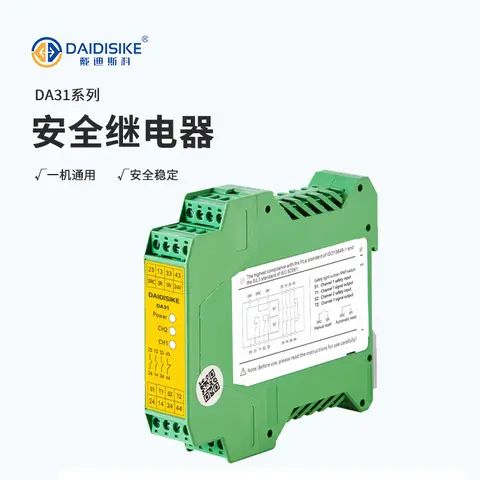
DA31 Emergency-Stop Safety Relay Module
Ultra-slim 22.6 mm Category 4/PL e/SIL 3 safety relay with dual-channel PNP/NPN input and a solid-state status output.
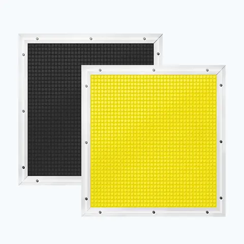
JT14 Safety Mat (Economical)
Economical pressure-sensitive safety mat with volt-free N.O. output for large-area or custom-shape floor guarding.
DX-C1 Magnetic Coded Safety Switch
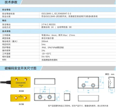
Non-contact coded-magnet safety switch with 17 mm sensing range and high misalignment tolerance for guard doors.